
LineWars VR Blog Posts
June 2nd, 2019 - New Main Menu Work Continues
This past month has been spent working on the new main menu scene of my game. After writing the previous blog post, I first worked on adding some global illumination for the station bridge. Since my idea is to have the station rotate, the amount of sunlight that reaches the station bridge interior changes all the time. When the bridge is in shadow, only light from the display panels should illuminate the environment, while the whole bridge should be quite bright when the sun is shining through all the windows. Thus, I needed a way to handle dynamic global illumination.
Dynamic Global Illumination
I had done something similar in my Cobra Cockpit already, so I took that system and began enhancing it. I decided to use all the four channels of the Vertex Colors to drive the global illumination. The Red channel tells how much this vertex gets light when the bridge floor is illuminated, the Green channel handles the left ceiling illumination, Blue channel the right ceiling, and Alpha channel tells how much static ambient lighting is affecting this vertex. The last channel is used to emulate light emitted from the display panels on the console tables and such. In my mesh import routine, I calculate and set up these vertex colors for each vertex that requires them (practically all of them do), and in the fragment shader I then calculate the combined global illumination value for the fragment like this:
shCol = col * dot(_GI, i.color) + oculusdither(i.vertex.xy);
The code uses just a simple dot product operation (which is basically the fastest GPU operation
there is) to multiply these vertex-specific illumination values with a uniform vector _GI, which
is calculated in the C# side. I am doing this dot product calculation in the fragment shader instead of
the vertex shader, because all the four vertex color channels may change independently along the polygon.
I also dither the end result, to get rid of any color banding on very low-lit areas.
The C# side calculates the _GI uniform value based on the current rotation of the station, and on some heuristics about how much sunlight will hit each side of the ceiling depending on the current rotation angle of the station.
        // Global illumination calculation
        float rotZ = stationTransform.rotation.eulerAngles.z;
        float giFloor = Vector3.Dot(lightDir, window_Nt);   // Floor illumination, use top windows normal
        float giLeft = 0f;
        float giRight = 0f;
        if (rotZ < 40f || rotZ > 250f)
        {
            giLeft = 0f;
            giRight = 0f;
        }
        else if (rotZ < 70f)
        {
            giLeft = (rotZ - 40f) / 30f;
            giRight = 0f;
        }
        else if (rotZ < 90f)
        {
            giLeft = (90f - rotZ) / 20f;
            giRight = (rotZ - 70f) / 20f;
        }
        else if (rotZ < 130f)
        {
            giLeft = 0f;
            giRight = (130f - rotZ) / 40f;  // Right ceiling from right side windows
        }
        else if (rotZ < 160f)
        {
            giLeft = 0f;
            giRight = 0f;
        }
        else if (rotZ < 200f)
        {
            giLeft = (rotZ - 160f) / 40f;   // Left ceiling from left side windows
            giRight = 0f;
        }
        else if (rotZ < 220f)
        {
            giLeft = (220f - rotZ) / 20f;
            giRight = (rotZ - 200f) / 20f;
        }
        else if (rotZ < 250f)
        {
            giLeft = 0f;
            giRight = (250f - rotZ) / 30f;
        }
#if false
        lowerDisplay.text = giLeft.ToString() + "\n" + giRight.ToString() + "\n" + rotZ.ToString();
#endif
        Vector4 gi = new Vector4(Mathf.Max(giFloor, 0f), Mathf.Max(giLeft, 0f), Mathf.Max(giRight, 0f), 1f);
        stationMat.SetVector("_GI", gi * giMult);
The giMult multiplier is for brightening things up on Oculus Go, which has very poor black levels.
I noticed I can help compensate for the poor black levels by brightening everything else up when running on Oculus Go.
It is quite a lot of work to determine the required global illumination values for each vertex, and I have so far done this only for a very small set of the vertices. It will take me a while to setup all these values for all the vertices in the bridge.
Floats in A Texture
I had already coded the main shadow planes (the walls with windows on them) into my vertex shader, but as with my Cruiser Bridge, I wanted to have additional shadows (caused by the display consoles, for example) as well. I had used a texture to contain the shadow plane information in my Cruiser Bridge vertex shader, with some scaling so I could use the 0..255 integer values in the texture as something like 0..2.55 meters with 1 cm granularity. That was OK for the Cruiser Bridge, but in my Space Station Bridge I needed more resolution. Is there an option to store higher resolution data to a texture?
It took me a while to figure out the correct Google search terms, but I finally found a way to store either 16-bit half floats or full 32-bit floats into textures, and load these in the vertex shader! This is generally supported in OpenGL ES 3.0, and Unity provides a check for support of these in the form of SystemInfo.SupportsTextureFormat(TextureFormat.RGBAHalf) and SystemInfo.SupportsTextureFormat(TextureFormat.RGBAFloat). I checked these on my Oculus Go and Samsung Galaxy S6 devices, and both of them support both of these formats, so I believe it is safe to use these in LineWars VR.
I decided to go with the 16-bit format, to save on bandwidth. I found a Wikipedia article describing the format, and showing some tables about the attainable precision. It felt like that precision would be enough for my uses, as my bridge is only a few meters wide. I should be able to get sub-centimeter precision for my shadows. After first tests, though, the precision did not seem to be sufficient. I wondered why, until I realized that my consoles are actually located around 50 meters down and 78 meters forward from the station origin! This meant that the precision of 16-bit floats is only 2-4 or 0.0625 meters (or 6.25cm), so much coarser than the sub-centimeter precision I thought I was getting! Luckily, this was easy to fix by translating the coordinates in the texture (by adding 50 to Y and subtracting 78 from Z before converting the values to 16-bit floats), and then restoring the coordinates in the vertex shader after loading them from the texture to full precision floats. This gave me approximately 2 mm precision for the shadows around the display consoles.
There were a couple of additional things I needed to do to be able to use the 16-bit floats. The first thing was that I needed to declare the texture in the shader as sampler2D_half instead of the normal plain sampler2D.
sampler2D_half _ShadowTex; // Use RGBAHalf texture format!
Another issue was that Unity (or actually C#) does not have a native 16-bit float type, and since I wanted
to generate the texture in code (during the mesh import phase), I needed to store the floats from Unity.
This turned out not to be much of a problem, as it can be done using a Mathf.FloatToHalf() helper method,
which actually returns the value as an ushort type. Since you can't perform any arithmetic with 16-bit
floats in Unity anyways, it does not matter that the value is unsigned short integer instead of a float. Storing
the ushort values into a texture is trivial. I decided to store the shadow texture data into
Assets/Resources/StationBridgeShadowData.bytes file, and then load the data into an actual texture when
the game is loading, like this:
    public const int SHADOWTEXWIDTH = 1024;

    private static Texture2D LoadShadowTexture()
    {
        Texture2D tex;
        byte[] bytes;
        tex = new Texture2D(SHADOWTEXWIDTH, 4, TextureFormat.RGBAHalf, false);
        bytes = Resources.Load<TextAsset>("StationBridgeShadowData").bytes;
        tex.LoadRawTextureData(bytes);
        tex.filterMode = FilterMode.Point;
        tex.Apply();
        return tex;
    }
We obviously want Point filter mode, so that the GPU does not attempt to smoothly interpolate
between the texture values.
The actual data in the shadow texture consists of basically the same data as I described in my Oct 19th, 2018 blog post Additional Shadows to Cruiser Bridge section. There are four rows of four floats in the texture, with the first row giving the shadow plane sizes (only two directions per plane), the second row contains the first plane normal and X center, third row has the second plane normal and X center, and the last row contains the center Y and Z coordinates for both the shadow planes.
In the vertex shader I first calculate the index into the texture. This is based on a vertex-specific value read from the UV Z-coordinate, plus adjustment based on the direction (quadrant) of the sunlight. This makes it possible to have the same polygon receive shadows from different planes depending on the sun direction, which increases the available shadow plane configurations per polygon. I can get by with checking just the X and Y coordinates, as the station rotates around the Z axis, so the Z coordinate of the sun light direction never changes.
fixed idx = v.uv.z + sign(_ShadowsLightDir.x)/8.0 + 0.125 + sign(_ShadowsLightDir.y)/4.0 + 0.25; // Texture index + light dir quadrant of the texture to use
Then it is just a matter of sending the shadow plane extents as-is to the fragment shader, and calculating the projection of the current vertex position (on both the shadow planes) into the shadowPos interpolator. I can use the sun quadrant calculation to take care of hiding shadows on the "wrong" side of the shadow plane, so I don't need to perform that check in the shader code.
    o.shadowData = tex2Dlod(_ShadowTex, float4(idx, 0/4.0 + 0.01, 0, 0));	// Get shadow plane extents (XZXY)
    half4 n1 = tex2Dlod(_ShadowTex, float4(idx, 1/4.0 + 0.01, 0, 0)); // Plane 1 normal + X center
    half4 n2 = tex2Dlod(_ShadowTex, float4(idx, 2/4.0 + 0.01, 0, 0)); // Plane 2 normal + X center
    float4 c = tex2Dlod(_ShadowTex, float4(idx, 3/4.0 + 0.01, 0, 0)) + float4(-50.0, 78.0, -50.0, 78.0); // Plane 1 yz and Plane 2 yz
    // We are only interested in the vertex position relative to the shadow plane center
    float3 a = v.vertex.xyz - float3(n1.w, c.x, c.y);
    float3 b = v.vertex.xyz - float3(n2.w, c.z, c.w);
    // Project the vertex onto the shadow planes
    a = a - dot(a, n1.xyz) / dot(_ShadowsLightDir, n1.xyz) * _ShadowsLightDir;
    b = b - dot(b, n2.xyz) / dot(_ShadowsLightDir, n2.xyz) * _ShadowsLightDir;
    o.shadowPos = float4(a.x, a.z, b.x, b.y);
The fragment shader then just compares the interpolators with the shadow extents, to determine if the fragment is in shadow. This code actually takes only 1 arithmetic GPU cycle (on ARM Mali T760), so it is quite a cheap shadow system. It does use two interpolators, so it takes 2 load/store cycles, though. Since my fragment shader still uses more arithmetic cycles than load/store cycles, the increased load/store operations do not actually matter.
    // First check the extra shadows from the shadow texture
    if ((abs(i.shadowPos.x) <= i.shadowData.x && abs(i.shadowPos.y) <= i.shadowData.y) ||
        (abs(i.shadowPos.z) <= i.shadowData.z && abs(i.shadowPos.w) <= i.shadowData.w))
        return shCol;
After I got this code working, I thought that since this is just the main menu of the game and thus is not quite as performance-critical as the actual missions, I could test how much of a performance hit would this system be if I doubled the available shadow planes! That is, if I used 1024x8 shadow texture instead of the 1024x4 shadow texture, and calculate all four shadow planes in the vertex and fragment shaders. I already knew how much slower the fragment shader would become, but I hadn't tested what is the performance hit of just my shadow system in the vertex shader.
I made the required changes, and used the Mali Offline Compiler to again check the cycle counts. With the original two texture shadow planes, the performance was like this:
  7 work registers used, 7 uniform registers used, spilling not used.

                          A       L/S     T       Bound
  Instructions Emitted:   48      21      4       A
  Shortest Path Cycles:   25.5    21      4       A
  Longest Path Cycles:    25.5    21      4       A
After adding the extra shadow planes, the performance dropped to this:
  8 work registers used, 7 uniform registers used, spilling not used.

                          A       L/S     T       Bound
  Instructions Emitted:   57      24      8       A
  Shortest Path Cycles:   29      24      8       A
  Longest Path Cycles:    29      24      8       A
So, twice the texture lookups, 3 additional load/store cycles, and 3.5 additional arithmetic cycles.
I decided to go with this setup, even though this vertex shader starts to be on the high end of the
acceptable performance of a mobile vertex shader. I can easily use up all the extra shadow planes,
as there are so many windows and various console tables and such on the bridge. Even these four
extra shadow planes are not enough to handle every shadow I would need, but it certainly helps.
Using Actual Weather Data
After I had decided on the contents of the display panels, and had done the station spin control panel and the holo radar range control panel, I began thinking about what other panels I could have in my control console. I still had more than half of the table top space unused, so what could I fill the space up with? It occurred to me, that a space station would need some environmental controls. Obviously, I don't have any way to affect the actual environment of the player, so I did not need to have anything the player could control, but at least some displays would be nice. I found out that the International Space Station uses pretty much the Earth standard atmosphere, so I could show numbers close to normal Earth atmosphere. But hey, the Earth atmosphere changes according to the current weather! How about showing the local weather in this panel! That would be more interesting than just some static values.
Okay, but how does one retrieve the current weather for use in a game? After some googling I found a neat example script for using OpenWeatherMap API in Unity. This example pretty much explained everything I needed. Retrieving the weather data close to the player location (without using the actual device location, which I did not get to work and would be unnecessarily invasive anyways) consists of three separate steps:
- Get the current public IP of the player's device
- Get the geographical latitude and longitude of the user's IP provider
- Get the weather information based on these coordinates
There are quite a few public API sites that return the public IP number of a user. For example, this StackOverflow reply lists many of them. Many of them have the option to return the IP as plain text, so I don't even need to have any JSON handling in my code for that. I used the Amazon service for my version:
    private System.Net.WebClient webClient = new System.Net.WebClient();
    private static string ipProvider = "http://checkip.amazonaws.com/";
    private string pubIp;

        pubIp = webClient.DownloadString(ipProvider);
        pubIp = pubIp.Trim();
By the way, your current public IP is:
The next step was to get the geographic location based on the IP address. For this, I used Geoplugin.com. This returns a JSON string, so I needed to add a simple JSON parser to parse the result. I decided to code my own parser instead of using some library, to keep things simple.
        string json = webClient.DownloadString("http://www.geoplugin.net/json.gp?ip=" + pubIp);
        float lat, lon;
        lat = GetJsonValue(json, "geoplugin_latitude");
        lon = GetJsonValue(json, "geoplugin_longitude");
My GetJsonValue helper method looks like this (it only handles float values, as that is all I need):
    private static float GetJsonValue(string json, string key)
    {
        int s, e, l;
        if (String.IsNullOrEmpty(json))
            return 0.0f;    // Not valid input!
        s = json.IndexOf(key);
        l = json.Length;
        if (s < 0)
            return 0.0f;    // Key not found
        s += key.Length;
        while (s < l && "0123456789.".IndexOf(json[s]) < 0)
            s++;
        e = s;
        while (e < l && "0123456789.-e".IndexOf(json[e]) >= 0) // CO pollution has values like 1.45e-07
            e++;
        float retval = 0f;
        float.TryParse(json.Substring(s, e - s), out retval);
        return retval;
    }
What remained was to get the actual weather data. This was pretty simple as well, except that since this call uses https instead of http, I needed to set a ServerCertificateValidationCallback to handle the certificate checking. I actually do not much care about the certificate (it does not matter if I get somehow faked weather report back), so I just accept all certificates in my code. I redacted my appId from the code below.
        System.Net.Security.RemoteCertificateValidationCallback curCB = System.Net.ServicePointManager.ServerCertificateValidationCallback;
        try
        {
            System.Net.ServicePointManager.ServerCertificateValidationCallback = delegate { return true; };
            json = webClient.DownloadString("https://api.openweathermap.org/data/2.5/weather?appid=[REDACTED]&lat=" + lat.ToString() + "&lon=" + lon.ToString());
            StationMenuScene.envTemp = GetJsonValue(json, "temp");
            StationMenuScene.envPres = GetJsonValue(json, "pressure");
            StationMenuScene.envHum = GetJsonValue(json, "humidity");
            json = webClient.DownloadString(String.Format("https://api.openweathermap.org/pollution/v1/co/{0},{1}/current.json?appid=[REDACTED]", (int)lat, (int)lon));
            StationMenuScene.envCO = GetJsonValue(json, "value") * 1000f;
        }
        finally
        {
            System.Net.ServicePointManager.ServerCertificateValidationCallback = curCB;
        }
In addition to the basic weather data, I also get the CO pollution levels, as I thought this might be
interesting info. The CO pollution levels are usually so low that I need to multiply by 1000 to get
some visible values in my bridge display panel (as it shows the data
per mille ‰).
I do all of this stuff when the game is loading, as otherwise these calls would cause frame rate hiccups.
Performance Info
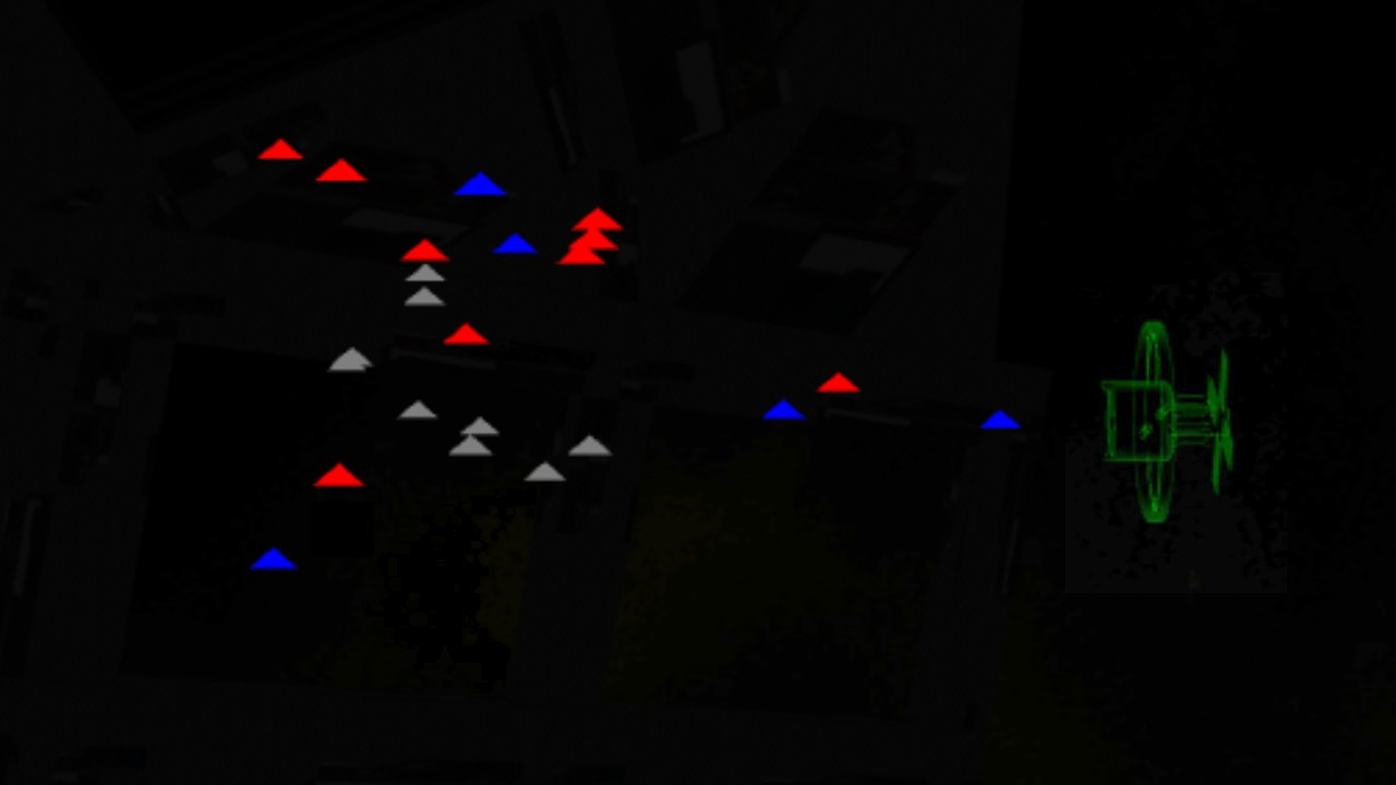
Speaking of frame rate, I found out that Oculus provides some performance info in the OVRManager class. So, I decided to display this on my console as well, calling it "Engineering" data. The OVRManager.display.appFramerate value shows the actual FPS, much like what the Oculus Performance Monitoring Tool displays. You can also get the current GPU usage from OVRManager.gpuUtilLevel, if the Boolean OVRManager.gpuUtilSupported returns true. I noticed that it returns True on Oculus Go, but False on Gear VR and Unity Editor. It is interesting info on Oculus Go, though. For the remaining slots in the Engineering panel I decided to show the screen refresh rate (72Hz on Oculus Go and 60Hz on Gear VR), and the current eye texture resolution (usually 1440x1440 when using the 1.4 render scale).
Freefall Comic
For my environment display I was looking for information about space habitat life support systems, especially the breathing atmosphere. I was wondering what oxygen levels and atmospheric pressures are normally used inside a space station. I found a very in-depth article about life support on Atomic Rocket pages. This article contained some comic strips, which seemed interesting, so I followed the link and found the Freefall comic by Mark Stanley (with color by George Peterson).
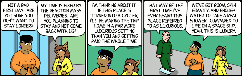
I started reading the comic from the beginning, and liked it quite a lot. It is smart and funny, so I thought it might actually be pretty fun if one of my Space Station Control Bridge display panels would show the latest Freefall strip! I contacted Mark Stanley, and got permission to include the latest comic strip into LineWars VR! The comic is visible on the "Instructions" panel (far left display) after clicking on the "FREEFALL" button. Other buttons on this panel are "INSTRUCTIONS" and "LEADERBOARD". To make the text as big and readable as possible, I added a shader that pans the comic strip left and right. This makes the best use of the display panel area, and simultaneously adds another animation thus making the display panels more interesting.
Bug in Native Code
When I was checking how my new Xbox Controller works with my Gear VR, I noticed something very strange. When I fired the laser before I had turned my ship at all, there was no laser rod visible! As soon as turned a little bit up or down, everything worked fine. Also, if I only turned left or right, the laser rod was visible, but had a wrong shape, it was like a plane instead of a rod! What was going on?
There were no problems when running the game in the editor, so obviously the bug was in my native code implementation of the laser handling. That was a pain to debug, as the native code only runs in the actual device, and not in the editor. Luckily, I was able to use the new status text panels of the main menu to help with the debugging. I was able to store some debug data within the native code in shared memory, and then read and display this data after returning to main menu. It still took me almost two full days of debugging before I finally found the problem.
In my C# code I check if a laser is active by checking the starting laser vertex against zero.
    if (startVertex == Vector3.zero)
        continue;
This is the same as checking for each of the coordinates for zero, like this:
    if (startVertex.x == 0f && startVertex.y == 0f && startVertex.z == 0f)
        continue;
When I converted that to my native assembler code, I knew that the zero value is the same as an integer
as a float, so I thought I could check if they all are zero simply like this:
1:  ldmia           r3, {r0-r2}                      // Load laser start to ARM registers (takes 2 CPU cycles)
    and             r0, r1
    ands            r0, r2
    beq             2f
If you are an experienced ASM programmer you will see the error, but I had just without thinking further
thought that since I use AND (&&) in the C# code, I could use AND in the ASM code as well.
However, to properly check if all the values are zero, you obviously need to OR them together!
So, the fixed ASM code is like this:
1:  ldmia           r3, {r0-r2}                      // Load laser start to ARM registers (takes 2 CPU cycles)
    orr             r0, r1
    orrs            r0, r2
    beq             2f
Well, that was silly, and a waste of a couple of days, but hopefully I will remember this in the future!
Main Menu Video Tour
For the past couple of days, I have been "fixing holes" in my main menu scene. That is so that I would be able to capture some video from it, to accompany this blog post. I had not worked on the rear of the bridge at all yet, so you could see the stars when you turned your head back in the main menu. That would be weird, so I had to do something about that. As I already had a raised platform and some stairs in my Cruiser Bridge object, I thought it would be easiest to do something similar for my Station Bridge as well. I quickly added some rear wall and a raised platform behind the console level, and then worked on some stairs and railings. These are still just very quickly modeled and textured polygons, missing a lot of fine-tuning. They were good enough to cover the stars, at least! Thus, I was able to record some video about the main menu.
That's it for this blog post! I'll continue modeling and texturing the main menu, and adding the missing shadow configurations, to make the shadows more realistic. When that is done, I'll need to work on the missing missions (only mission 8 is completely missing, all the other single player missions are already at least running). Almost all the multiplayer missions are also still missing, and then there is a lot of polishing up to do. So, several months still before the game gets released! Thank you again for your interest in my LineWars VR project!
Apr 28th, 2019 - Multiplayer and New Main Menu Work
During the past month I have been focusing on two things, first getting the multiplayer system to work, and then revamping the main menu of the game. I had worked on multiplayer up the point where I could have a VoIP conversation with a remote party, and the main menu has until now been just a very plain 2D menu. It took me 10 days to get the multiplayer system working, and the rest of the time I have been focusing on the main menu.
Multiplayer Work
Immediately after writing the previous blog post I began designing the multiplayer system. I had downloaded the Photon networking Unity Asset earlier, but I was still not sure whether that was the way to proceed. I also took a look at the Unity FPS Sample, especially the video about the networking techniques.
The FPS Sample had a rather complex data transmission system, where the server updates the world using unreliable UDP protocol, and thus needs to handle missing and/or duplicate packets, keep track of the network latency, etcetera. It also delta-compresses the data to send, which is a good idea in theory, especially on PC platform, but I was afraid complex compression and delta calculation on mobile platform might cause its own problems. In any case, first I needed to determine what data I need to send for each ship to be able to keep the game state in sync across the network. I came up with the following list of values:
  - Data needed to send for ShipStruct:
    - rot + pos = Quaternion + Vector3 = 4+3 floats = 28 bytes (matrix would be 3*4 floats = 48 bytes)
    - CurSpeed (float)

    - MoveMode (1 bit, DroidMove or MissileMove)
    - CMove1 (3 bits)
    - MissilesLeft (3 bits)
    - ForeShield (byte) (cruiser shield max = 80 * 256, so divided by 256)
    - AftShield (byte)
    - HullDamage (byte) (alien mothership damage max = 250)

    - ShipIdx (6 bits, 0..63)
    - ShotByIdx (6 bits, 0..62, 63=-1)
    - TargetIdx (6 bits, 0..62, 63=-1)
    - NavTargetIdx (6 bits, 0..62, 63=-1)
    - EquipmentDamage (7 bits, 0..127)
  - Total 28 + 4 + 1 + 1 + 1 + (1+6+6+6+2+3+3 bits = 4 bytes) = 39 bytes per ship
To make the data divisible by 32 bits, I added one byte, so I ended up with fitting all state data for each ship into 40 bytes. The UDP packet is supposed to be less than 1500 bytes, so I could send data for up to 37 ships in one packet. Not quite up to the 64 ships that I can have in each of my missions. However, if each network party sends data for the ships it controls and receives data for the ships the other parties control, I could easily fit up to 32 ships into a single packet. Most of the missions even have various static objects like asteroids that do not need their data be transferred, only information about whether the object is alive. To handle this, I added a 64-bit alive vector to the packet, to let the other parties know which ships this party thinks are still alive.
I found a neat trick from the Unity FPS Sample regarding how to efficiently send data consisting of multiple data types. Marshalling a structure is a somewhat heavy operation and involves copying data around. Since the lower level packet routines use byte arrays, that would be the native format to send. However, my data consists mostly of floats and some integers. How to convert this into a byte array efficiently? The FPS Sample used structures with overlapping field offsets, much like the union structures from the C language. I added a static temporary buffer that could be both an array of floats and an array of unsigned integers, which made it easy to build my data packet as a simple array.
    [StructLayout(LayoutKind.Explicit)]
    struct UIntFloatArray
    {
        [FieldOffset(0)]
        public float[] floats;
        [FieldOffset(0)]
        public uint[] uints;
    }

    static readonly UIntFloatArray tmpBuffer = new UIntFloatArray { floats = new float[DATA_SIZE / 4] }; // 10 uints = 40 bytes per ship
Converting this array to a byte array was also quite simple using Buffer.BlockCopy, like this:
Buffer.BlockCopy(tmpBuffer.uints, 0, byteBuffer, byteOffset, DATA_SIZE);
This actually copies both floats and unsigned integers. As long as the remote side knows which indices contain floats
and which contain integers, it is easy to copy the byte data back to floats and unsigned integers on the receive side.
Instead of using Photon or a client-server system like the FPS Sample, I decided to use peer-to-peer networking. Each of the parties (or both of the parties, as for now I went with just 2 player networking) control their own ships, and receive data for the ships the other side controls. To make things simple, I divided the ships based on their array number to even and odd ships, so that one side controls the even-numbered ships and the other side controls the odd-numbered ships. I also thought that letting the player to teleport into any ship would be a sure way to cause a race condition across the network, so I decided to limit the player to only teleport into odd- or even-numbered friendly ships. On Player-versus-Player missions the ships will be naturally divided between the players, and on co-operation missions this just means that each player has their own set of friendly ships (sort of like "lives" they can spend).
I added code to transmit and receive network packets using a peer-to-peer connection. A received packet is checked for every frame, and every fourth frame a new packet is sent. This makes the data transfer run at 15 times per second or 18 times per second (Gear VR at 60fps or Oculus Go at 72fps). I did not think the difference between 15 and 18 times per second would be much of an issue, as the network is in general unreliable and variable, so my networking code should not have trouble receiving packets at any frequency.
After working on this for five days, I was ready for the first multiplayer tests, between my Oculus Go and Gear VR. I did not have any latency control yet, I just sent the current ship positions and rotations, which obviously caused quite jittery movement. So, the next step was to figure out some way to handle variable network latency. This was such a difficult problem I spent several days just experimenting with various options and techniques.
Movement Smoothing
I started work on smoothing the ship movement using the player-controlled ship. Since the ship always moves forward based on its speed, I thought this should be an easy problem to solve. And indeed, I got reasonably good results just by using the speed and direction of the ship during the frames no new network packet was received, and then adjusting the position based on the just received packet. However, the variable network latency caused the ship to jump forward and/or back whenever a new packet was received. I began coding some adjustment based on the calculated packet delay, but it soon became obvious this gets quite complex very quickly.
Instead of checking for the network delay, I thought about filtering the ship position, just like any noisy input can be filtered to get a smooth result. Instead of using the world position of the received packet, I decided to convert the new position to local coordinates of the ship, and then translating the current ship position towards this local target position. The local position tells how far from the remote position the current local position of the ship is.
Using just some empirical testing, I noticed that by filtering the ship position X and Y coordinates by 0.2 (so they would reach the correct position in 5 frames), and the Z coordinate (which is most affected by the ship's current speed) by 0.5 * Time.deltaTime (so it would take 2 seconds to reach the correct position), I got quite smooth motion. The remote-controlled ship seemed to still follow the steering inputs reasonably fast.
Okay, now the player-controlled ship was handled, how about the AI-controlled ships? Since both sides of the network use the same code for controlling the AI ships, I thought they should stay pretty well in sync if I let both sides control all the AI-controlled ships, and just adjust the position if it got too much out of sync. Somewhat to my surprise, this did not seem to work at all. The ships jumped every which way, and most of the time seemed to even fly sideways, as it looked like the network parties had completely different ideas about which enemy ships should the AI-controlled ships target!
Okay, so that was not a good idea. Since the player-controlled ship worked well using just some motion smoothing, I decided to abandon the idea of having both sides control all AI-controlled ships, instead I gave full control of the AI ships to whichever party was responsible for that ship. I used the same smoothing factors as with the player-controlled ship, and that finally made the droid ships also move quite smoothly. The code that runs every frame for these ships is actually quite simple:
    Vector3 p = Movement.shipData[idx].netPos; // Use the most recently received local position of where we should be
    float spd = (Movement.shipArray[idx].CurSpeed + p.z * 0.5f) * Time.deltaTime;
    tr.Translate(new Vector3(p.x * 0.2f, p.y * 0.2f, spd)); // Move us towards where we should be
    tr.rotation = Quaternion.Slerp(tr.rotation, Movement.shipData[idx].netRot, 0.2f);
In the above code, netPos is the most recently received position (in local coordinates of the ship's
local position at the time we received the packet) of where we are supposed to be, netRot is similarly
the rotation we should have, and tr is the GameObject.transform of the ship we are moving.
Firing Lasers and Missiles
Okay, now the ships moved nice and smooth, but they did not shoot yet. What would be the best way to transfer all the laser beams and also the missiles? They both move so fast that I felt using a similar movement smoothing might not work all that well. In addition to that, as the ship positions were smoothed and they were based on some old state on the other party, the actual ship positions might be quite far from where they seemed to be. I remembered an old conversation from back in 1995, when I played a lot a multiplayer game called Warbirds. There were some angry players who thought the game cheated, when they collided with another plane and they were the only one to die, with the other plane flying away. The game programmers explained that all collisions are handled from the front-end perspective, so you only die if your front end sees a collision. I thought I might use something similar in my game.
I decided to experiment with a system where lasers and missiles are both handled completely locally. The network is only used for getting info about the player pressing the fire button, or launching a missile. For the AI-controlled ships I went even further, so that ships that are remote controlled even make a decision to shoot a laser locally. This way they shoot only when they point at a target, which might happen at quite different times between the local and remote game. Moving the laser beams and the missiles, and checking whether they hit anything, is also done locally. Since I already transmit EquipmentDamage and HullDamage for each ship, I simply used the more damaged version (local versus remote) of these for each ship. If a ship dies on either side, that information will be transmitted in the next packet using the alive bit vector, so the ship will very soon die on the other side as well.
This system is obviously not very accurate, but I found out that it does not matter. When a player shoots at a ship, regardless of the target ship being locally or remotely controlled, the lasers hit when it looks like they should. The ship gets destroyed after a few hits just like in single player missions. The missiles may take a completely different path locally than remotely, but it does not matter all that much either, as the ship gets destroyed if the missile hits on either side of the network. If the missile hits some obstacle before it hits the target, it gets destroyed (without usually causing that much damage to the unfortunate target). This may make it occasionally seem like the missile just blows up without hitting anything, but you rarely have time to wonder about that in the heat of the battle.
Finishing Touches
Okay, now I was able to play a mission between my Oculus Go and Gear VR devices, but my system did not yet handle mission death or victory, nor had any possibility to choose a mission and things like that. To handle these, I added a PacketType byte in the header of my packet. I thought just three different packet types should be enough, so I created an enum for these:
    public enum PacketType
    {
        MainMenu = 0,
        GameRequest,
        GameData
    };
The GameData packet is what I had been working on, so I just needed to add handlers for the two additional
packet types. The MainMenu packet gets transmitted when the players just sit in the main menu. It has no extra
data content yet. In case I feel like adding the option to text chat while on the main menu (in addition to the
current VoIP system), I could easily add the written text into this packet. This could be used to discuss and
agree on which mission to start and so on.
The GameRequest packet is sent, when the player has selected a multiplayer mission to play. It contains the mission number that was selected, and also the mission number that the remote side has selected. This is to detect possible race conditions, when both players choose a mission to play at the same time. In this situation the players may have chosen different missions, so this conflict needs to be resolved. I decided to simply choose the lowest-numbered multiplayer mission to start in this case. The switch case that handles the received GameRequest packet ended up being rather simple:
        switch (remoteState)
        {
            case PacketType.GameRequest:
                switch (localState)
                {
                    case PacketType.MainMenu:
                        // The remote side has requested a game, while we are just sitting in the main menu.
                        // Tell we accept the request!
                        remGameReq = recvBuffer[GAME_REQ_OFFS];
                        myGameReq = remGameReq;
                        localState = PacketType.GameRequest;
                        return;
                    case PacketType.GameRequest:
                        // Both sides have sent/received a game request! Use the lowest-numbered game to launch.
                        remGameReq = recvBuffer[GAME_REQ_OFFS];
                        if (myGameReq > remGameReq)
                            myGameReq = remGameReq;
                        if (recvBuffer[GAME_REQ_ACK_OFFS] > 0)
                        {
                            // If the remote side has seen our game request packet, we are ready to go to the actual game!
                            MainMenuScene.LaunchScene(gameNames[myGameReq], false);
                        }
                        return;
                    case PacketType.GameData:
                        // We are in game but the remote side is still at the game request state.
                        // Just wait for the other side to catch up.
                        haveNewPacket = false;
                        return;
                }
                return;
        ...
When testing this system, I again noticed how my Oculus Go seems to be much slower than my Gear VR on Samsung Galaxy S6.
When I launched the mission on Oculus Go, my Gear VR had already been waiting with the game running for 5 seconds when
my Oculus Go finally had managed to start the mission. It took about 3 seconds for my Gear VR to launch the mission, while
my Oculus Go spent 8 seconds for the same. I think this is pretty curious.
After I got all this code working, I contacted a friend of mine who has been helping me test my game from the beginning. We launched our games, went into multiplayer, and started up the only multiplayer mission I had done, a co-op version of the "Mission 2: First Blood". We had some issues early on where the VoIP connection did not seem to work properly, but after a few tries everything worked fine, and we were able to play all the 10 levels of this mission. My friend did not notice anything strange about the ship movements or laser and missile firing, so I took that as a good indicator that my system works also in the real world. So, all that remained was just adding more multiplayer missions. Instead of continuing with this, though, I decided to tackle another big issue that has been on my TODO list forever, revamping the main menu of the game.
New Main Menu
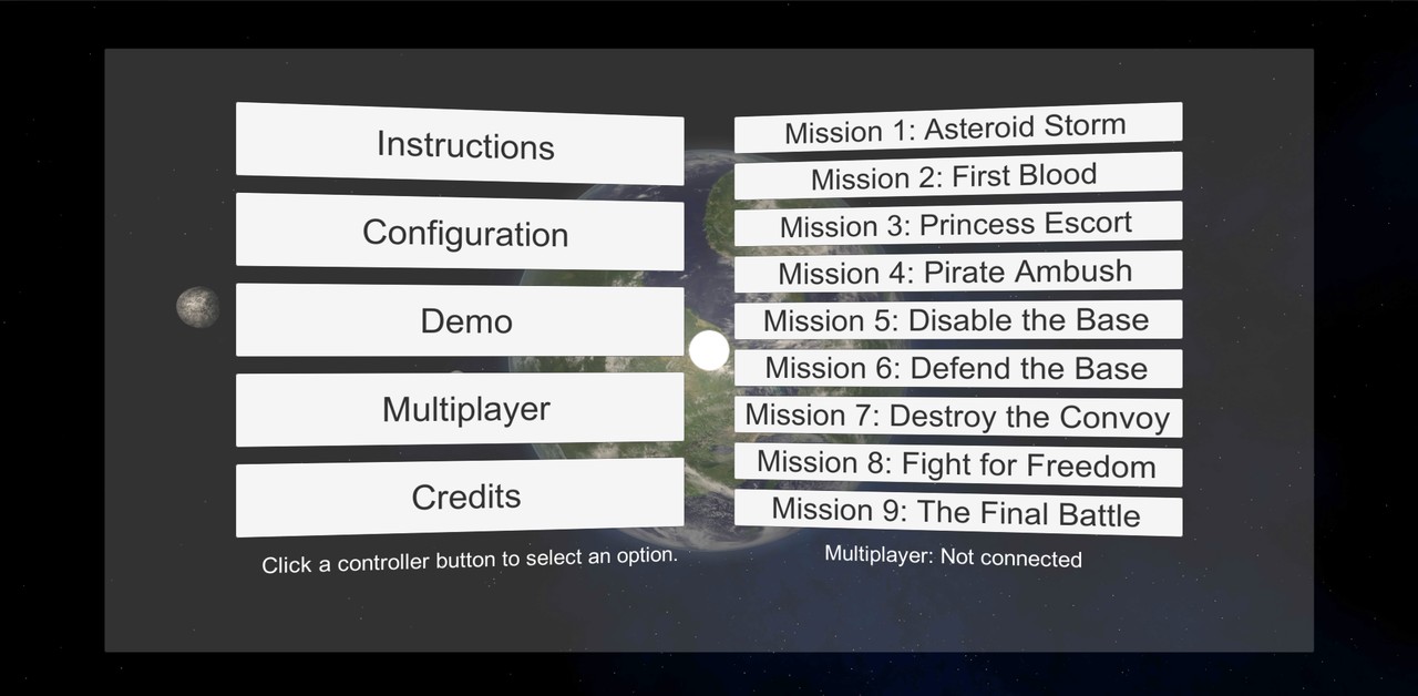
After I got the first real multiplayer test successfully done, it was time to do something to the main menu, which has until now been just a simple placeholder. It was based on one of the earliest VR samples, so it was originally gaze-controlled. It was also using a lot of Unity Canvas and Button objects, which were basically meant for 2D menus. I had not done any proper configuration screens or such yet, as I knew I wanted to redo the main menu, so I decided now was the time for that. The original main menu looked like this:
Space Station Command and Control Bridge
When thinking about options for a new better menu scene, I got an idea of having the main menu environment be the Space Station Command and Control bridge. There are two such bridges in my space station, on opposite sides across the "mail slot" where the ships fly in and out of the station. Both of the bridges have windows looking forward and also windows looking "up" (towards the station spin axis) across the "mail slot". I thought it might look pretty cool if the player would sit in this bridge, and could look ahead and/or up through those windows, while the space station keeps on rotating. I could even show off my shadow technology here, with the sun shining through the windows and creating moving shadow patterns on the floor!The first step was to take my Space Station mesh object in Cinema 4D, and check how big those bridge extrusions actually are. The floor level of the bridge extrusion is 18.26 meters wide, 4.3 meters high, and 11.2 meters deep, which should make it quite a good size for such a main menu environment. I copied out the parts of the space station that would be visible from the Command and Control bridge windows, and began modeling the actual windows. The windows in my original Space Station mesh were just painted in the texture, so I used that texture and modeled the actual windows into my new StationBridge mesh.
With the windows in place, next it was time to add some "furniture" on the bridge. I copied the Weapons Officer console from my Cruiser mesh, and added four those on the bridge. This still left room to have a big holo radar in the middle of the bridge. I copied the holo radar from my Cruiser Bridge, just doubled the size. The holo sphere in the Cruiser Bridge has a 2.5-meter diameter, on the StationBridge it is 5 meters in diameter. This fits even though the front part of the bridge is only 4.3 meters high, as the bridge has a sloped ceiling which grows up to 6 meters high towards the center of the bridge.
Command Console Display Panels
In my original 2D menu clicking on the left side menu items changed what the right side of the menu displays. Thus, I had actually 6 separate screens (or canvases) in my original main menu. The Cruiser Weapons Officer console had four large and two small display panels, but it was only two-sided, sort of L shaped. If I made the console be U shaped (or sort of upside-down U, if you understand my meaning), I could fit 6 large display panels in addition to the 2 small panels, so I could fit all the original canvas panels on these display panels! That seemed like a good idea, so I began designing these display panels.
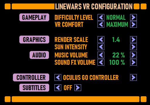
I had a long time ago come across a Start Trek fan site called LCARSCom.net. I actually used some images I found there as reference for my Cruiser Weapons Officer display panels. Now I went to this site again, in an attempt to figure out some suitable theme for my display panels. I looked into various panels in their gallery, until I found out that I actually liked most the site design itself! So, I borrowed some ideas from that, including the color table they used, and came up with some quite nice-looking display panels for my bridge. I did not want to use the same font as the LCARS site used, so I searched the fonts I got installed on my Windows for a somewhat similar very narrow font. I found a font called Bahnscrift Condensed, which seemed to be just what I was after. Here is a very preliminary image of what the configuration display panel might look like. The actual configurable options might still change, but something like this they would most likely be:
I also added a panel for selecting the mission to play (which is pretty much the main purpose of this main menu scene), but that panel looked rather plain and empty. How to make it look more interesting? Before I had this Space Station Bridge idea, I had thought about having a short video clip of each of the missions run in the corresponding main menu button background. How about having the video clips run in this mission select display panel, much like the chapter select pages of some DVD movie discs work? My instrument panel texture dimensions are 2048x2048, and I used only 512x360 pixels for each of these six display panels, so I had a lot of space left over. I could have 32 frames of 64-pixel wide animations running, but you can't fit much video into 32 frames. That would only be about half a second, so it would be over very quickly. However, I had already used some texture Lerping in my explosion animation, which smoothly interpolates between adjacent animation frames to make the video run longer. I wondered how far I could extend this.
I noticed that I could actually drop down to 8 frames per second and still make the video look reasonably smooth, so that meant I could have 4 seconds of video in those 32 frames! That should be enough for such a (practically useless) visual enhancement. I added code into my instrument display shader to handle these animations. I allocated the bottom half of the texture for animations, leaving the top half for static textures. Obviously, I could have split the texture in two, and have separate shaders, gameobjects, etcetera, but I like to use as few game objects, textures and shaders as possible, even when I need to make shaders a bit more complex. I have learned that the GPU runs code much faster than the CPU for things like these, so it is better to spend some extra GPU cycles to save a lot of CPU cycles.
This is what the vertex shader code that handles the looping animations looks like:
if (v.uv.y < 1024.0/2048.0)
{
    // Calculate the frame we are to show. We run the animations at 8 fps
    float t = ((uint(floor(_Time.y * 8))) % 32) / 32.0;
    float f = frac(_Time.y * 8);
    o.uv = float4(v.uv.x + t, v.uv.y, f, 1);
}
else
    o.uv = float4(v.uv, 0, 0);
The uv.x coordinate is adjusted in the vertex shader to point at the correct frame in the animation, based
on the current time. I send the current lerp factor in the uv.z item, and the uv.w item works as a flag
to let the fragment shader skip the rest of the code when this fragment is not animated. The fragment shader code
looks like this:
    half4 tex1 = tex2D (_MainTex, i.uv.xy);
    if (i.uv.w < 0.5)
        return tex1; // Normal triangle
    // Smooth animation between the adjacent video frames
    half4 tex2 = tex2D (_MainTex, i.uv.xy + float2(1.0/32.0, 0));
    return lerp(tex1,tex2,i.uv.z);
Now I just needed to record some video from my missions that I could then show in this mission selection display panel. I went back to my trusty old Avisynth scripts, and began experimenting. I used some of the clips I had recorded in the beginning of this year for my trailer, as those were still on my hard disk. I just cropped and resized these suitably, added some borders (so the video looks like it is running in a window inside the display panel), and also realized that I could use the StackHorizontal Avisynth built-in command to have adjacent frames already stacked in the video. I could have stacked all 32 frames, but that made it very slow to scan through the video in VirtualDub, so I decided to go with 8 adjacent frames. This meant I just needed to "Copy source frame to clipboard" 4 times in VirtualDub, and then paste these 8 adjacent frames from the clipboard into my texture. This part was very easy and fast, it just took a lot longer to find a good part of the recordings to use. Here below is the Avisynth script I used for these video clips:
# Useful area for 64x55 video = 1048x900
LoadPlugin("C:\Program Files (x86)\AviSynth\plugins\ffms2-2.23.1-msvc\x86\ffms2.dll")
#FFMpegSource2("g:\OwnVideos\2019-01-30_09-04-14.mkv").Crop(436, 112, 1048, 900) # Mission 1 footage from trailer, frames 1510..
#FFMpegSource2("g:\OwnVideos\2019-04-13_16-14-21.mkv").Crop(300, 112, 1048, 900) # New Mission 2 footage, frames 360..
#FFMpegSource2("g:\OwnVideos\2019-04-13_11-13-43.mkv").Crop(436, 112, 1048, 900) # New Mission 3 footage, frames 734..
#FFMpegSource2("g:\OwnVideos\2019-01-31_07-39-16.mkv").Crop(436, 112, 1048, 900) # Mission 4 footage from trailer, frames 832..
FFMpegSource2("g:\OwnVideos\2019-04-24_16-20-06.mkv").Crop(100, 112, 1048, 900) # New Mission 9 footage, frames 603..
Levels(0, 1.4, 255, 0, 255) # Make the video brighter using gamma 1.4
Lanczos4Resize(60,50)
AddBorders(2, 2, 2, 2, 255*65536+153*256) # Colored 2-pixel border around the frame, so 60x50 => 64x54 frame size
a = SelectEvery(8,0) # Drop from 60 fps down to 7.5 fps
b = a.Trim(1, 10000)
c = a.Trim(2, 10000)
d = a.Trim(3, 10000)
e = a.Trim(4, 10000)
f = a.Trim(5, 10000)
g = a.Trim(6, 10000)
h = a.Trim(7, 10000)
v = StackHorizontal(a, b, c, d, e, f, g, h) # 8 adjacent frames stacked horizontally
return v
After adding those short video clips for a couple of the missions, I noticed that I still have a lot of room left over in the instrument panel texture. I thought it might be a good idea to show an animated controller for the ship orientation control, in the "Ship Controls" display panel. My alpha testers seem to not have had any problems controlling the ship, so this was probably not necessary, but I thought it would make the display panel much livelier. Thus, I used the meshes that came with the Oculus Integration package for the Gear VR and the Oculus Go Controllers, made some animations from them, and recorded some video from running these animations in Unity. Then I used a similar system to the above Avisynth script to convert these videos also into 32-frame 64x54 animation frames. I was actually able to make both the Roll and Pitch animations only 32 pixels wide, so I could fit both of those into a single 64x54 slot in my texture. I think the end result was pretty neat.
Station Spin Speed Control
Now that I had the control console display panels figured out, I wanted to test what it looked like sitting in front of a console in a command bridge of a rotating space station. I added code to rotate the bridge, and started up the scene. The experience was otherwise fine, but it was a bit nauseating even for a VR veteran like myself to be inside a spinning wheel. That was a bit of a disappointment, as my whole idea was to have the station spinning. But it would not be nice to cause VR sickness as early as in the main menu of my game!
I had used the default station spin speed of 5 degrees per second when testing the scene. I had actually not calculated how fast my space station should spin, so perhaps that is too fast a speed, for causing 1G of centripetal force inside the habitation ring? I adjusted the spin speed to 2 degrees / second, and the experience was much less nauseating, it was actually pretty fun watching the star field slowly rotate around. But, let's calculate what the actual spin speed should be. I found a Wikipedia article called Rotating Wheel Space Station which had a formula for calculating the artificial gravity resulting from the spin:
a = −ω2r
That is, the gravity is based on the square of the angular velocity times radius. As I was not sure about the units, I searched for some examples, and found Stanford Torus proposal from 1975, which is 1800 meters in diameter and rotates once per minute. Checking the formula against that, it was clear that the angular velocity was measured in radians per second, and the radius in meters. Using my space station habitation ring radius of 139 meters, I found out that the station should rotate at 15.2 degrees/second! So over three times faster than my first test, which already caused nausea! How could I solve this problem?
Well, how about letting the player choose the space station spin speed? If they are veteran VR players and do not get VR sickness easily, they could let the space station rotate at 15 degrees/second, but if they have a weak stomach, they could even stop the rotation completely. I did not want to add this configuration into the actual game configuration display, as this affects only the main menu, so I decided to have the in-game Space Station Command Console have controls for the station spin speed. I thought that was a fun idea, so began implementing this right away. I added buttons to decrease and increase the spin speed with 0.5 degrees/second granularity, and also additional numeric displays for the actual spin speed (as it takes time for the station to spin up or down to the requested speed), and the resulting artificial gravity on three levels of the station: Habitation Wheel, Hangar Deck and the Command and Control Deck.
After I got the spin speed control to work, I spent some time coding the window shadow planes into my station bridge shader. These turned out to be about as complex as the Cruiser Bridge shadow configuration, which runs fine. This meant that performance-wise the window shadows should work fine also in the main menu. The moving shadows on the floor and walls while the station spins looked pretty neat! Sadly, all my texturing (and much of my modeling) is still at such early stages I can't show you any videos about that yet. I also need to add more detailed shadow configuration, much like in my Cruiser Bridge, as there are also other objects causing shadows besides just the window rims.
Holographic Radar
After I got the station spinning and also the shadows to work, I wanted to add the radar code. My idea was that this main menu is not just a static environment, instead I could replace my original Demo Mission with this new main menu! That meant the player would be sitting in the command bridge, watching Cobra fighters getting launched from the station and defending the station against some attacking Pirate fighters. This of course meant the holographic radar in the middle of the command bridge should be working, and displaying all the fighter ships furballing around the station. I could copy much of this code from my actual missions, so making the radar work was not much of a problem. However, when the space station itself was also represented by a small blip in the radar, you could not tell any distances, or even determine which of the blips is the space station. Could I represent the space station itself better in the radar?
My space station mesh in Unity has 6373 vertices and 4676 triangles, and it is my most complex mesh. I did not want to spend this much from the vertex/triangle budget to have a miniature space station shown on the radar, but I could probably simplify this mesh quite a bit for a small version of it. I went to work making a lower-poly version of my Space Station mesh, and ended up with a mesh having 1447 vertices and 2208 triangles. Less than half the triangles and less than quarter the vertices, so that was quite a bit lighter on resources. I scaled this version of the space station mesh to 1/1000, called it "TinyStation" and imported it into Unity. I put it in the middle of the radar, attached my transparent Shield shader to it, and started up my scene. It already looked pretty good!
Having a proper model of the space station in the middle of the radar was also very useful to give completely new players an idea of where they are when they are in the main menu. Looking at the radar, they can pretty easily figure out they are inside the space station, and when they look up through the windows, they will see the Cobra fighters launching above them. However, the station was rather small and indistinct in the radar, when it was in correct scale relative to the rest of the scene. What if that scale was adjustable? That would make another main menu -specific configuration option, which would be good as that makes my command console have more controls that actually work!
Since the radar diameter was 5 meters, and my TinyStation object was scaled 1/1000, it meant the radar could see a sphere 5 kilometers in diameter. Since the space station habitation ring has a diameter of 278 meters, the largest fraction of that 1/1000 scale where it still fits inside the 5 meters radar sphere would be around 1/56. That would not make much sense, though, as the idea is to show the fighter ships around the station. I decided to have selectable scales of 1/2000, 1/1000, 1/500, 1/250 and 1/125, which correspond to radar ranges of 5000m, 2500m, 1250m, 625m and 312.5 meters. The holo radar scale adjustment panel I came up with shows the range, scale, and also the number of friendly, enemy, and other objects (asteroids) inside the selected range.
That's about all I have had time to get done during the last month! I'll continue modeling and texturing the main menu scene, but it will probably take me at least another month before it is in any presentable shape. We shall see... Thank you again for your interest in my LineWars VR game and this blog!
Mar 31st, 2019 - Status Update
Lots of varied progress during the past month, so I could not figure out a better title to this blog post than a plain "Status Update". Let's get on with the update!
Cruiser PDC Handling to Native Code
As I had been working on improving the performance even before I wrote the previous blog post, and as the new Mission 7 I started work on needed to have several cruisers firing their PDC guns, I decided to check how much of a performance hit does the Cruiser PDC gun moving and firing actually cause. It turned out that the PointPDC code (which determines where to point each PDC gun) took between 0.1 and 0.5 milliseconds, depending on how many guns need moving. That was for a single cruiser, so with several cruisers in the scene that could jump up to several milliseconds. That is rather high, considering that at 72fps everything that happens in a frame needs to fit within about 13.8 milliseconds, including all the rendering that needs to be done. Thus, I decided to port this code over to native C code.
The reason I hadn't ported this code over earlier, was that I needed to access the positions and directions of all the close enemy ships, and I also used a lot of Quaternion routines like LookRotation and RotateTowards in the code. I had to figure out a way to do all that in C code, without accessing the Unity C# helper routines. I decided to use a Matrix to pass the location and direction data of all the ships to the native code. To do that I split my existing ShipData class array into two separate structure arrays, ShipArray for data containing only such structures that can be passed to native code, and ShipData for an array of data consisting of C# class instance pointers. I added Matrix4x4 structures called l2wm (for LocalToWorldMatrix) and w2lm (for WorldToLocalMatrix) into the ShipArray array, so that I can access the positions and directions of all the ships also in the native code. I just need to remember to assign the matrix from the transform of the gameObject once per frame, like this:
    shipArray[idx].l2wm = shipData[idx].gameObject.transform.localToWorldMatrix;
    shipArray[idx].w2lm = shipArray[idx].l2wm.inverse;
Now I could easily transform the ship positions between the local coordinate systems of each of my ships, or specifically transform the world coordinates of the ships into the local coordinate system of my Cruisers in order to aim the PDC guns correctly. For example, when in C# I would write Vector3 outPoint = shipData[idx].gameObject.transform.InverseTransformPoint(inPoint), in my native code I could do the same thing by calling TransformPoint(&outPoint, &inPoint, &(shipArray[idx].w2lm)). I added the following helper functions into my native code to perform such transforms for a point and for a direction vector. I did not handle scale here, as practically all my objects have no scaling:
static inline void TransformPoint(VECTOR3 *o, VECTOR3 *p, MATRIX4X4 *m)
{
    o->x = p->y * m->col[1].x + p->x * m->col[0].x + p->z * m->col[2].x + m->col[3].x;
    o->y = p->y * m->col[1].y + p->x * m->col[0].y + p->z * m->col[2].y + m->col[3].y;
    o->z = p->y * m->col[1].z + p->x * m->col[0].z + p->z * m->col[2].z + m->col[3].z;
}

static inline void TransformDirection(VECTOR3 *o, VECTOR3 *d, MATRIX4X4 *m)
{
    o->x = d->y * m->col[1].x + d->x * m->col[0].x + d->z * m->col[2].x;
    o->y = d->y * m->col[1].y + d->x * m->col[0].y + d->z * m->col[2].y;
    o->z = d->y * m->col[1].z + d->x * m->col[0].z + d->z * m->col[2].z;
}
Okay, that was part of the problem solved, but I still needed to replace the Quaternion operations with something else, to get all my PDC code ported to native C code. I could perhaps have used matrices instead, but I did not want to figure out how to do all those LookRotation and such operations using matrices, so I decided to look into what those Quaternion routines actually do.
The first step was to find out how a vector multiplication by a quaternion works. I found implementations of various Quaternion functions from OGRE3D source codes. These included the vector multiplication, which I then implemented in plain C language for my native code, as follows:
// Based on https://github.com/ehsan/ogre/blob/master/OgreMain/src/OgreQuaternion.cpp
static inline void QuatMul(VECTOR3 *o, QUATERNION *q, VECTOR3 *v)
{
    // nVidia SDK implementation
    VECTOR3 uv, uuv;
    //Vector3 qvec(x, y, z);
    //uv = qvec.crossProduct(v);
    uv.x = q->y * v->z - q->z * v->y;
    uv.y = q->z * v->x - q->x * v->z;
    uv.z = q->x * v->y - q->y * v->x;
    //uuv = qvec.crossProduct(uv);
    uuv.x = q->y * uv.z - q->z * uv.y;
    uuv.y = q->z * uv.x - q->x * uv.z;
    uuv.z = q->x * uv.y - q->y * uv.x;
    //uv *= (2.0f * w);
    //uuv *= 2.0f;
    //return v + uv + uuv;
    o->x = v->x + 2.0 * q->w * uv.x + 2.0 * uuv.x;
    o->y = v->y + 2.0 * q->w * uv.y + 2.0 * uuv.y;
    o->z = v->z + 2.0 * q->w * uv.z + 2.0 * uuv.z;
}
Next, I looked for the LookRotation implementation, and found an algorithm from Unity Answers, where someone had implemented the code in C#. I converted this algorithm to C for my uses. I am not sure if this is the most efficient way to do this, but it seems to work. I might still implement all of these in NEON ASM if needed, to get them to run even faster.
// Implementation of Quaternion.LookRotation, based on https://answers.unity.com/questions/467614/what-is-the-source-code-of-quaternionlookrotation.html
// NOTE! f and u vectors need to be normalized!
static inline void LookRotation(QUATERNION *o, VECTOR3 *f, VECTOR3 *u)
{
    VECTOR3 vector2, vector3;
    float m00, m01, m02, m10, m11, m12, m20, m21, m22, num, num2, num3, num4, num5, num6, num7, num8;

    // Vector3.Cross(up, Vector3.Normalize(forward))
    vector2.x = u->y * f->z - u->z * f->y;
    vector2.y = u->z * f->x - u->x * f->z;
    vector2.z = u->x * f->y - u->y * f->x;
    // vector2 = Vector3.Normalize(Vector3.Cross(up, vector));
    m00 = 1.0 / sqrt(V3DOT(vector2, vector2));
    vector2.x *= m00;
    vector2.y *= m00;
    vector2.z *= m00;
    // vector3 = Vector3.Cross(vector, vector2);
    vector3.x = f->y * vector2.z - f->z * vector2.y;
    vector3.y = f->z * vector2.x - f->x * vector2.z;
    vector3.z = f->x * vector2.y - f->y * vector2.x;

    m00 = vector2.x;
    m01 = vector2.y;
    m02 = vector2.z;
    m10 = vector3.x;
    m11 = vector3.y;
    m12 = vector3.z;
    m20 = f->x;
    m21 = f->y;
    m22 = f->z;

    num8 = (m00 + m11) + m22;
    if (num8 > 0.0)
    {
        num = sqrt(num8 + 1.0);
        o->w = num * 0.5;
        num = 0.5 / num;
        o->x = (m12 - m21) * num;
        o->y = (m20 - m02) * num;
        o->z = (m01 - m10) * num;
        return;
    }
    if ((m00 >= m11) && (m00 >= m22))
    {
        num7 = sqrt(((1.0 + m00) - m11) - m22);
        num4 = 0.5 / num7;
        o->x = 0.5 * num7;
        o->y = (m01 + m10) * num4;
        o->z = (m02 + m20) * num4;
        o->w = (m12 - m21) * num4;
        return;
    }
    if (m11 > m22)
    {
        num6 = sqrt(((1.0 + m11) - m00) - m22);
        num3 = 0.5 / num6;
        o->x = (m10+ m01) * num3;
        o->y = 0.5 * num6;
        o->z = (m21 + m12) * num3;
        o->w = (m20 - m02) * num3;
        return;
    }
    num5 = sqrt(((1.0 + m22) - m00) - m11);
    num2 = 0.5 / num5;
    o->x = (m20 + m02) * num2;
    o->y = (m21 + m12) * num2;
    o->z = 0.5 * num5;
    o->w = (m01 - m10) * num2;
}
Another algorithm I needed was the RotateTowards algorithm, to get the PDC gun turrets to slowly rotate towards the enemy ships they are shooting at. I also needed to know the angle difference between the current angle of the gun and the target angle, so I implemented my version of the code to return the angle difference to the caller. Thus, I do not need to calculate this separately, as I had to do in my C# code.
// From http://www.opengl-tutorial.org/intermediate-tutorials/tutorial-17-quaternions/
// The function returns the angle difference between q and q2
static inline float RotateTowards(QUATERNION *o, QUATERNION *q, QUATERNION *q2, float maxAngle)
{
    float cosTheta, angle, fT, t1, t2, t3;
    QUATERNION q1;

    q1.x = q->x;
    q1.y = q->y;
    q1.z = q->z;
    q1.w = q->w;

    //cosTheta = dot(q1, q2);
    cosTheta = q1.w * q2->w + q1.x * q2->x + q1.y * q2->y + q1.z * q2->z;

    // Avoid taking the long path around the sphere
    if (cosTheta < 0)
    {
        q1.x = -q1.x;
        q1.y = -q1.y;
        q1.z = -q1.z;
        q1.w = -q1.w;
        cosTheta = -cosTheta;
    }
    angle = acos(cosTheta);

    if (maxAngle < 0.001)
    {
        o->x = q->x;
        o->y = q->y;
        o->z = q->z;
        o->w = q->w;
        return angle;
    }
    // q1 and q2 are already equal, or the difference is less than we are allowed.
    if (cosTheta > 0.9999 || angle < maxAngle)
    {
        o->x = q2->x;
        o->y = q2->y;
        o->z = q2->z;
        o->w = q2->w;
        return angle;
    }

    fT = maxAngle / angle;

    //quat res = (sin((1.0f - fT) * maxAngle) * q1 + sin(fT * maxAngle) * q2) / sin(maxAngle);
    t1 = sin((1.0 - fT) * maxAngle);
    t2 = sin(fT * maxAngle);
    t3 = 1.0 / sin(maxAngle);
    o->x = (t1 * q1.x + t2 * q2->x) * t3;
    o->y = (t1 * q1.y + t2 * q2->y) * t3;
    o->z = (t1 * q1.z + t2 * q2->z) * t3;
    o->w = (t1 * q1.w + t2 * q2->w) * t3;

    //res = normalize(res);
    t1 = 1.0 / sqrt(o->x * o->x + o->y * o->y + o->z * o->z + o->w * o->w);
    o->x *= t1;
    o->y *= t1;
    o->z *= t1;
    o->w *= t1;
    return angle;
}
After I had implemented all those, it began to look to me like actually handling the rotation of each of the vertices of the PDC gun mesh would be faster using the TransformDirection() routine using a rotation matrix, instead of doing this using a Quaternion. My understanding has been that Quaternions are used because they are fast, but looking at these implementations it seemed that multiplying a Vector with a Quaternion needs 21 multiplications, while matrix multiplication only needs 9 multiplication operations. So, I decided to add code to convert the Quaternion into a rotation matrix after I had calculated the direction where the gun should point at, and before performing the actual vertex adjustment. This code is also based on the OGRE3D source codes.
// From https://github.com/ehsan/ogre/blob/master/OgreMain/src/OgreQuaternion.cpp
static inline void Quat2Mat(MATRIX4X4 *o, QUATERNION *q)
{
    float fTx  = q->x + q->x;
    float fTy  = q->y + q->y;
    float fTz  = q->z + q->z;
    float fTwx = fTx * q->w;
    float fTwy = fTy * q->w;
    float fTwz = fTz * q->w;
    float fTxx = fTx * q->x;
    float fTxy = fTy * q->x;
    float fTxz = fTz * q->x;
    float fTyy = fTy * q->y;
    float fTyz = fTz * q->y;
    float fTzz = fTz * q->z;

    o->col[0].x = 1.0f-(fTyy+fTzz);
    o->col[1].x = fTxy-fTwz;
    o->col[2].x = fTxz+fTwy;
    o->col[0].y = fTxy+fTwz;
    o->col[1].y = 1.0f-(fTxx+fTzz);
    o->col[2].y = fTyz-fTwx;
    o->col[0].z = fTxz-fTwy;
    o->col[1].z = fTyz+fTwx;
    o->col[2].z = 1.0f-(fTxx+fTyy);
}
Using all of these helper routines I was able to port the whole PDC gun pointing and shooting code over to native code. I timed the native code performance using the Unity profiler, and it gave around 8x performance boost over the C# version. This time the performance improvement was not quite 10x, as much of the inner code was just copying vertex positions from one array to another, which is not much faster in native code.
Oculus Go Performance Issues Continued
I ended my last blog post mentioning how I still suffered some frame drops even after "precompiling" all my scripts. After I got the PDC gun handling ported to native code, I decided to continue troubleshooting these performance issues. I disabled various parts of the code, but could not get rid of the frame drops. It then occurred to me to check what kind of performance End Space (which I consider to be the main competition for my game) has on my Oculus Go. I was pretty surprised to see that even though End Space forces both CPU and GPU levels to as high as they can be set, it still suffers from major frame drops. The frame drops in End Space were much more severe than in my game, even though I used much lower CPU and GPU levels with higher resolution.
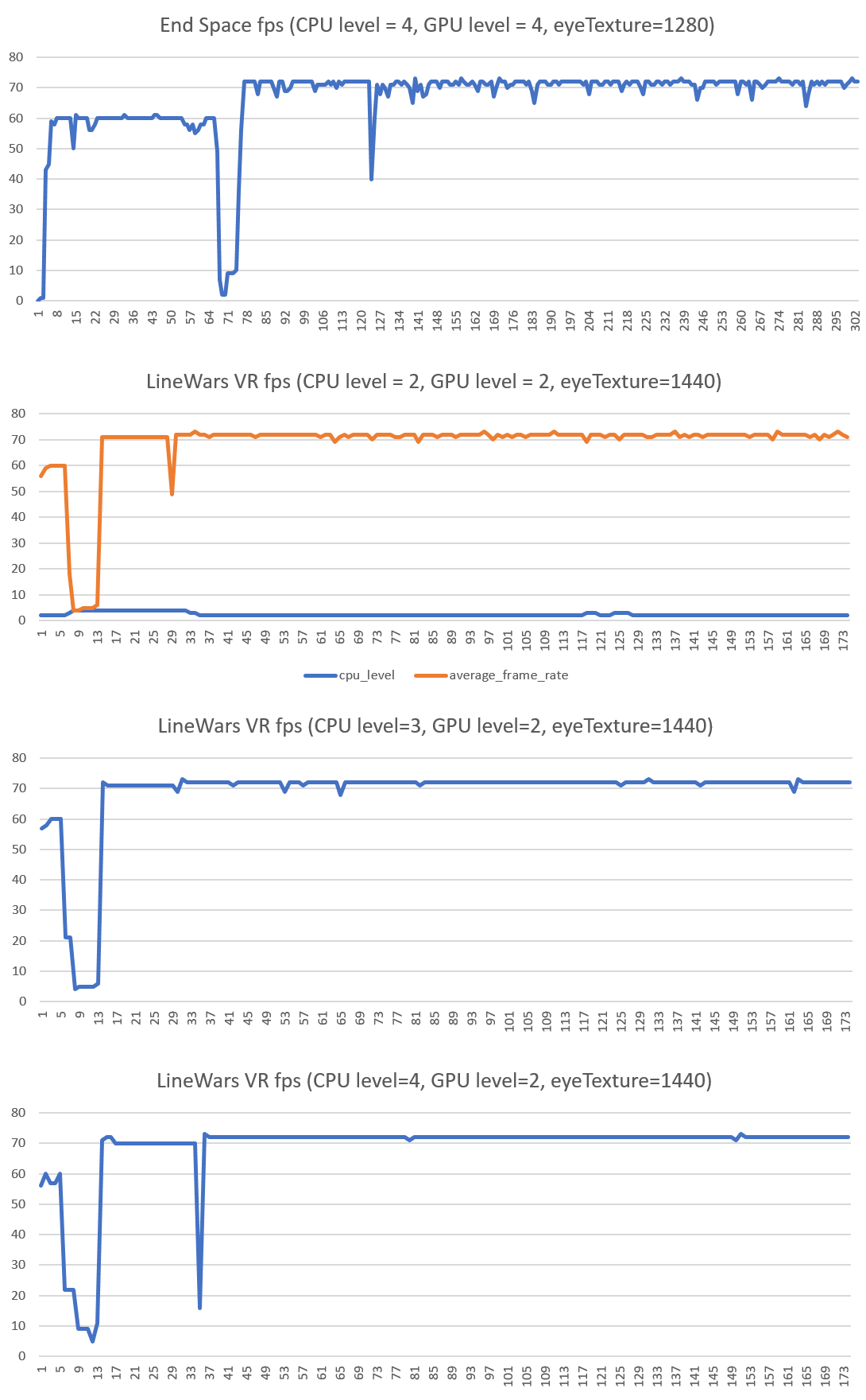
As you can see from the above graph (second from top), when running LineWars VR at CPU level 2, I get almost constant frame drops. Looking at the CPU level graph it seems like the dynamic throttling does not work quite as it should. Most of the time the CPU does not dynamically switch to a higher level, even though that might avoid a frame drop. Checking End Space finally made me test how my game behaves with forcing CPU level to 4 (which basically disables dynamic throttling). This got almost completely rid of the frame drops, and visually the gameplay was also very smooth. So, it seems like dynamic throttling just does not play well with my game. Increasing GPU level has practically no effect on the framerate, so I can leave that at the default level of 2.
I decided to use this CPU=4 GPU=2 level combination on Oculus Go from now on. I still want to port the slowest methods over to native code, but it looks like I can already reach quite steady 72fps when using CPU level 4. The device gets a bit warmer than it did on level 2, and the battery consumption increases, but as the gameplay is much smoother, I think this is an acceptable tradeoff.
Mission 7 Work
Okay, now that the performance issues were again mostly solved, I could get back to working on Mission 7. When porting the PDC code over to native code, I had checked all the algorithms I needed to change to handle several cruisers shooting their PDC guns, so now it was time to implement these changes. This worked quite fine, except that now the mission became much too difficult! With the enemy cruisers having their main gun active and all of them shooting their PDC guns, it took only a short while for them to kill all the friendly fighters and also the player's ship! That was no fun.
I decided that the enemy convoy cruisers will not actively use their main guns against the attacking friendlies, instead they rely on the escort fighters and their PDC guns to kill the attackers. This made the mission somewhat easier, but still those PDC guns did short work of the attackers. I decided to test reducing the PDC gun firing speed, and that turned out to be a good way to balance the PDC gun effectiveness. With the PDC fire speed reduced (compared to Mission 3, where the cruiser is friendly) the PDC fire in Mission 7 was survivable enough that the mission is winnable. It does get rather challenging towards the higher levels, with more enemy cruisers and also more escort fighters in the convoy. Since there are only two missions remaining after this one, I think it is OK for this mission to be somewhat challenging.
Alien Mothership
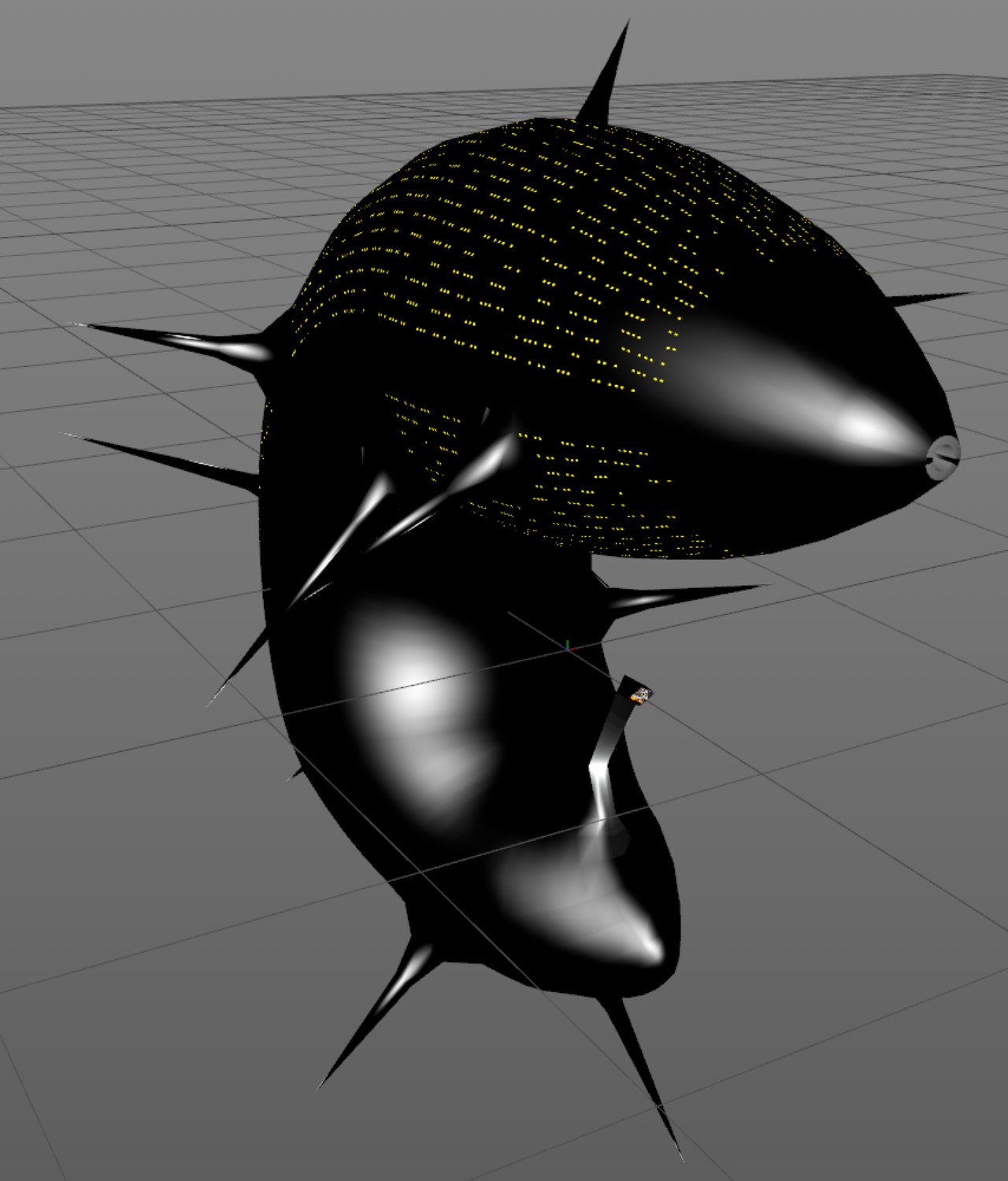
For missions 8 and 9 I needed an Alien Mothership object. I have been thinking about this object for a few months now, but have not been able to come up with anything that I would be happy with. One morning I did yet another Google image search about alien motherships, and this time I finally found an image that gave me an inspiration for the look of my Alien Motherships! I wanted to have a ship design that looks organic and asymmetric, and quite sinister and intimidating. I also decided to make this ship mostly black, with a lot of specular shininess on it. To help with the sense of scale, I added a lot of small windows on the top part of the ship.
The Alien Mothership currently has 1487 vertices and 2106 triangles, which is a bit on the heavy side in terms of collision detection. As I use mesh collisions using a KDtree approach, so many triangles make the corresponding KDTree to have 760 nodes in the KDtree, so it takes a bit too much CPU time to handle the collision detection. As the object is very irregularly shaped, there is even no good way to limit the required collision tests. I will probably attempt to reduce the polygon count of this object still further before releasing the game.
This is what the Alien Mothership currently looks like. It is still missing some texturing, but the overall look is like in this image.
Mission 9 Work
I decided to skip Mission 8 for now and move directly to Mission 9 "The Final Battle". This is a desperate battle to save the Earth from an alien invasion. I have very rarely managed to win this mission in my original LineWars II game, and it should be almost unwinnable also in LineWars VR. But not quite unwinnable, as that would be cheating, in my opinion. In my original game the alien motherships were escorted by Cobra fighters, but I thought that does not make much sense story-wise, so I decided to create some specifically alien escort fighters for this mission.
I decided to create simple black shiny spheres as the alien drone ships. These are very small (currently only 2 meters in radius) and very fast (only a slightly slower than the missiles) and super manoeuverable. In addition to this, they shoot faster than the fighter ships and have no engine trails. Thus, they are very difficult to see (them being black with no trails) and difficult to shoot at (them being faster and much more manoeuverable than your ships). However, they are not very durable, and the PDC guns of the friendly cruisers can track them, especially when they fly straight towards the cruiser. These drones are very annoying to try to shoot at, and I think that suits my goal of making this mission very difficult and desperate-feeling.
What makes these drones even more annoying is that the Alien Motherships launch new drones to replace any killed drones. Thus, in this mission you need to kill (the VERY tough and hard to kill!) Alien Motherships first, if you wish to have any chance of surviving the mission! The Alien Motherships are quite heavily armed themselves, they have lasers that will kill a fighter in one shot, and will severely damage even a cruiser with every shot. In addition to this, the Alien mothership does not need to face the target it is shooting at, unlike the fighter ships and alien drones. Luckily the Alien Motherships only use their lasers for close range defense, so if you stay away from the mothership, it will most likely not shoot at you.
I also worked on the skybox for Mission 9. Since this mission happens around Earth, it should have the Earth in the background, and I also wanted to have the correct star map (as seen from Earth) in the skybox. This will of course not look quite as nice as some colorful nebulas I have in other missions, but perhaps such dark background increases the darkness and desperation of this mission. I would like to have both the Earth and the Moon in the skybox, but if I use realistic sizes of them, either one or both of them would be pretty small. Perhaps I will exaggerate the size of the Moon to make it look nicer in the skybox.
All in all, Mission 9 turned out to be very action-packed, with several cruisers shooting their PDC guns, and dozens of drones and around 15 friendly fighters mixing it up in a large furball around the cruisers. Quite like what I was aiming for with this mission! I tried to take some screen shots, but as static screenshots don't show the action at all, they do not look very good. I also don't want to spoil the mission by posting a video of it, so I don't have anything to show for this mission at the moment, sorry.
An Article About Me and LineWars VR in a Local Newspaper!
The local newspaper Keskisuomalainen wrote an article about me and my LineWars VR game. The article came out on the 27th of March. That was some nice free publicity for my game, even though the audience was somewhat limited, the newspaper being a local one. My game is targeted to global audience, but any publicity is good publicity, as they say! There was even a small picture on the front page of the newspaper, which was a nice bonus!

That's it for this blog post! Thanks again for your interest in my game and in this blog! I will continue fine-tuning Mission 9, then work on Mission 8, and after that I should be able to focus on the multiplayer features. Then there are a lot of bugs to fix and minor improvements to texturing and other aspects of the game to do before I can get it finished, so the release is still several months away.
Mar 3rd, 2019 - Cruiser Death Handling, Multiplayer Work, Oculus Go Performance Issues
Cruiser Death handling
After I got the trailer released, I began working on Mission 7, where the goal is to destroy an enemy convoy consisting of several cruisers. I could not get very far with this mission, as there was no way yet to kill the cruisers. You could only damage them, but there was no cruiser death handling implemented yet. Thus, in order to get further in my game, I needed to implement a death handling for a cruiser.
I first started experimenting with some kind of an explosion when the cruiser dies, something like what I had for the asteroids. However, this seemed quite difficult to get looking in any way convincing, and I also had trouble figuring out how the exploded fragments would then vanish from the scene. With the asteroid it is sort of expected that the fragments crumble and thus get smaller and smaller and then vanish, but why would some exploded parts of a ship do that? If I did not make the fragments disappear, though, I would need to keep them alive for the duration of the scene, and that would make them also need collision handling, you should be able to shoot at them, and so on. This seemed like a lot of work.
In the end I decided to have the cruiser just explode into two parts, so it kind of gets cut in half. This way I only needed to model two fragments, and I decided it would be OK if these parts would just stay in the scene tumbling, and you could actually collide with these tumbling hulks. I used the fire animation on most of the body panels of these destroyed parts, so they look like the remnants of a big explosion that cut the ship in half. I still need to fix the texturing (and perhaps also the modeling) of the area closest to where the explosion happened, but other than that, the parts seem to work okay.
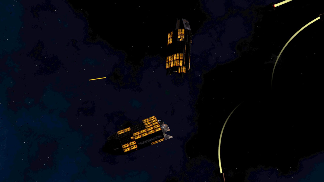
I still need to work on improving my PDC gun handling to allow several cruisers in the scene, for the Mission 7 to work properly. Currently I only have one array for cruiser PDC targets, but when there are several cruisers in the scene, these all should have their own targets for their PDCs.
Multiplayer Work
I also decided it was high time for me to start at least looking into the multiplayer features of LineWars VR. As it is rather difficult to get started with such a major feature, I thought I'd start simple, and first look into getting VoIP working between two players.
I looked into the Oculus VrVoiceChat sample that is included in the Oculus Unity Integration package. It seemed to suit my needs pretty well, so I implemented a similar Oculus Rooms -based system, where you can invite a friend that also has LineWars VR into a room that you created, and then a VoIP connection is automatically created between the two players. I am having some issues with this yet, and it seems like there are some issues with the Oculus forums as well, as many replies to similar questions seem to be missing. For example How to remove room invites forcefully. Anyways, the issues I am currently having are:
- When using the Oculus-provided user invitation list, it is not apparent how do you actually invite users. Both me and a friend I tested with assumed just clicking on a user sends an invite, however, you need to click on the small +-sign on the right of the friend name. This is not a technical issue, just a UI problem on the Oculus side.
- When the user launches a game based on the invite, the game is supposed to get a callback attached by Rooms.SetRoomInviteAcceptedNotificationCallback() method. However, no such callback seems to ever happen.
- I don't know how to acknowledge the room invite (delete it from the queue of notifications). There seems to be a way to do that, but it is not mentioned in the documentation, and the forum thread I found asking about this issue does not have the replies visible.
Working around the above issues, though, allowed me to have a VoIP conversation with a friend while we both played the game. The next step is obviously to add some networking code to allow the players to play in the same game. I planned to start working on this next, however, the performance problems I had been having with my Oculus Go made me want to look into those first.
Oculus Go Performance Issues
Since I received the Oculus Start Development Kit early last month, I have been testing my game on the Oculus Go. I was expecting Oculus Go to be in many ways better than my Samsung Galaxy S6 using the Gear VR device, however it seemed the opposite was true. This is what my impressions with Oculus Go were, compared to my Gear VR:
- The picture quality of Oculus Go is much worse, mainly because of the poor black levels. There are actually no blacks on the screen, the best you can get is dark gray. This made my game look very washed out, as deep blacks would be very important in a space game. Also, Oculus Go uses Fresnel-type lenses, which I find to have all sorts of reflections and other issues (like god rays, though they do not seem to be much of a problem in Oculus Go).
- The built-in "headphones" obviously have poor sound quality compared to proper headphones I need to use with the Gear VR. Thus, my game does not sound nearly as good or immersive on Oculus Go as it does on Gear VR.
- The Oculus Go controller touchpad is rather finicky, and often fails to recognize presses on the top part of the touchpad. This is an issue in my game, as I use that area for throttle up.
- To top it all off, even the performance of Oculus Go seemed to be worse than my Galaxy S6 (which is the slowest supported device for Gear VR)!
I actually spent about two weeks fighting with the performance issues, which did not seem to make much sense. I got big frame drops even in the main menu of the game, which only had a few buttons and nothing else. I even tested with hiding everything from the main menu, except the camera and the skybox, and STILL I got constant dropped frames, as in the following graph!
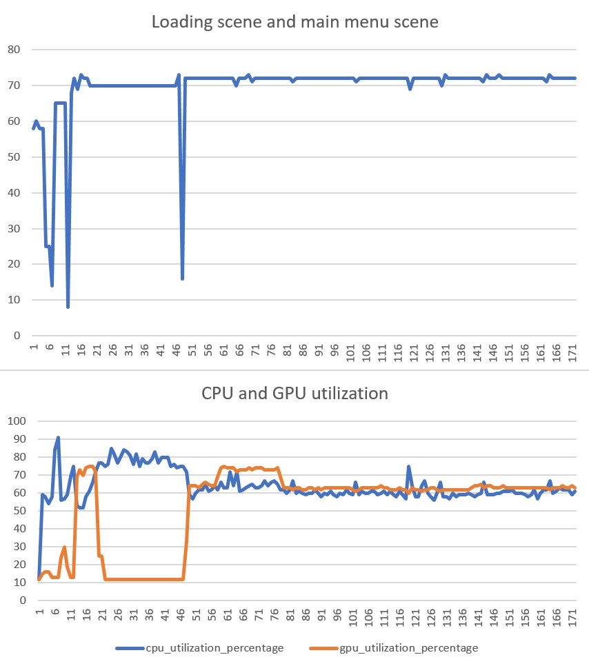
In the above image you can see the graphs from my loading screen and then the main menu. The loading screen looks rather normal, with the constant CPU load causing the framerate to drop to 70fps, and the GPU not doing much of anything. When the main menu begins, though, there are occasional CPU jumps from the base level of 60% usage to about 65% usage or above, and each of these jumps seems to immediately cause frame drops! I just could not figure out how such a small CPU usage increase would immediately drop frames, and what would even cause such periodic CPU usage increase when just sitting in the main menu?!
After a few days of not getting any further with the frame drops in the main menu, I decided to focus on the actual game instead. I used the profiler to look into code that takes a lot of time to execute. Here also there were some very strange results, where a simple code that normally takes almost no time suddenly took several milliseconds to run. This below is what the average frame rate graph looked like when playing the actual game.
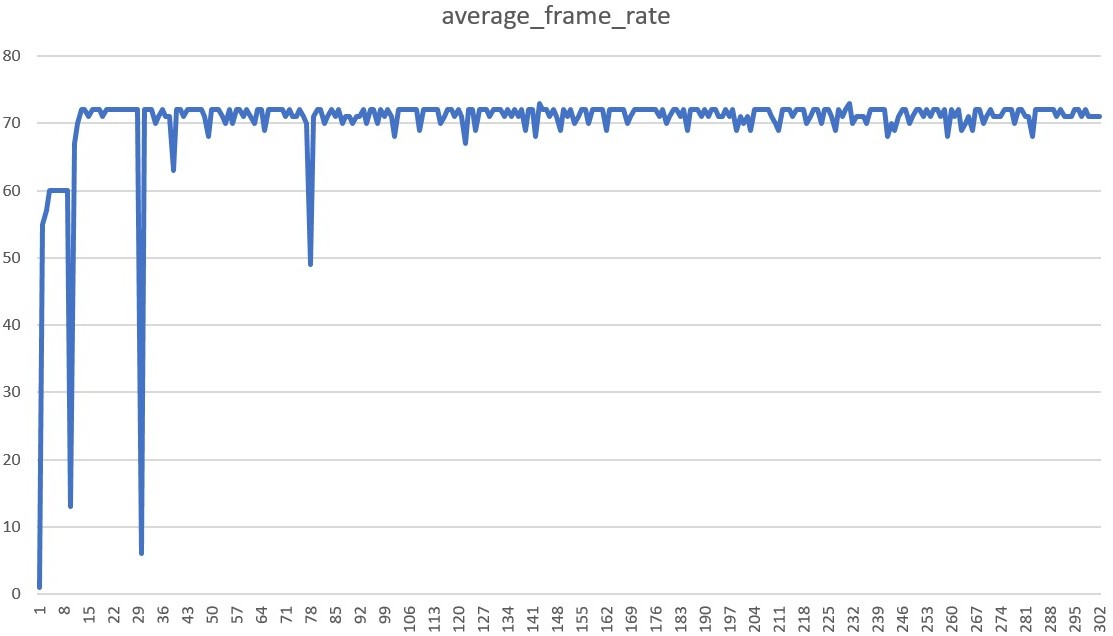
After adding some UnityEngine.Profiling.Profiler.BeginSample() calls into my code, I noticed that the code that handles the cockpit instruments seemed to sometimes take quite a lot of time to run. When digging deeper into this code, it turned out that the problem was the CrosshairsCheck code, which sends a ray forward from the player's ship, and checks what the ray hits. I am using my own KDTree implementation for the ray-mesh intersection tests, and when the target was a space station (my most complex object), this test took a lot of time (0.80ms or over 80% of all the time spent in all my scripts) even on the PC, which is about 10 times faster than the Oculus Go! That was not good.
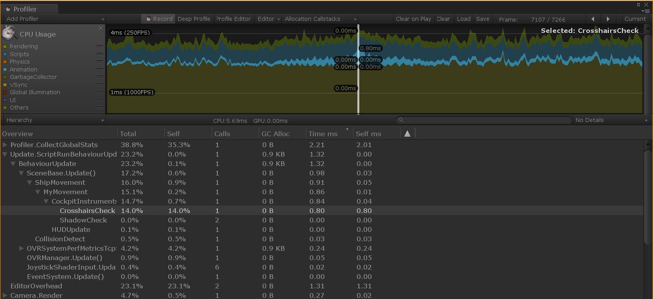
I realized that the KDHit test routine I had written in C# code was a good candidate for porting over to native code. I did that, and after that change this test took less than 0.1ms to run on the Oculus Go. This did not fix my main performance issues, though.
After a lot more tests it began to look like every time I activated a new game object, there was a frame drop. Thus, I began changing my object pools to not actually contain disabled GameObjects, but instead have all the GameObjects active, but just scaled to zero. This of course increases the number of draw calls. Since I do not seem to be bound by anything graphics related, instead by some Unity GameObject activation-related issue, I thought this might be a good trade-off. While I was doing this, I also decided to switch my "AsteroidHit" handling (which actually does not have much to do with asteroids, it is just an animated sprite that displays a flash and some ejecta from any kind of hit to a ship hull or asteroid) to use native code. I created just a single GameObject to contain 20 separate square "panels", each by default having a zero size. These panels can then be located in world coordinates where such a hit animation needs to be shown at, and rotated and scaled to face the camera. Thus, I did not need to have any GameObject activation when such a hit happens. This improved the frame drops somewhat, but still many frame drops remained.
Finally, after I had fought with this problem for almost two weeks, it occurred to me to check what would happen if I switched my background music from "Streaming" to "Compressed in memory" in the Unity audio clip settings. To my surprise, this finally got rid of the periodic frame drops in the main menu, and also improved the frame drops in game quite noticeably! I had assumed that the background music streaming would happen in a separate thread, so it had not even occurred to me that playing music could be the reason for my frame drops! After this change, and including some (but not all) of my GameObject activation changes, I got the following frame rate graph (showing the loading screen, main menu, and start of a mission, including a level change). So, not quite a straight line yet in the actual mission, but much better than what I had managed before.
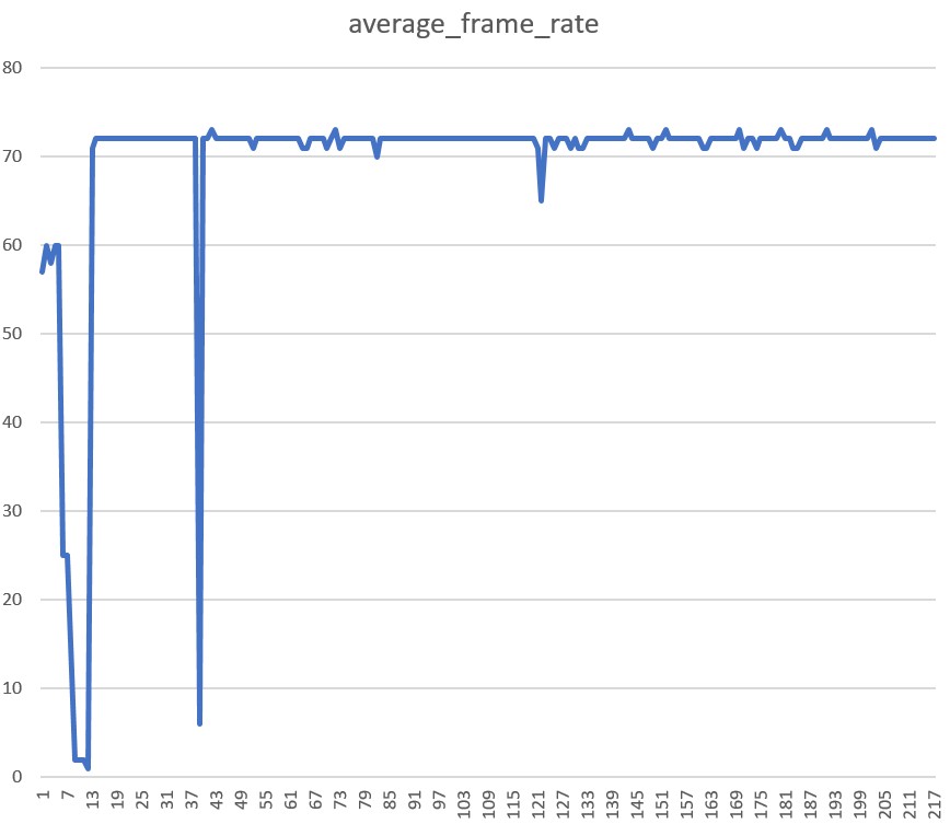
I still had an issue of an occasional sudden major frame drop. I began to suspect this was some kind of Just-In-Time compiler issue, where the first run of any code takes a lot longer than subsequent runs. This would be a problem in my game, as there are a lot of complex code that gets executed when something specific (like a collision) happens. If the first collision always causes frame drops, that would be pretty bad. I decided to properly test this theory, using my Mission 9 scene which I had not finished yet. I made the scene contain only three ships, which fly towards each other at their maximum speed, so they all collide with each other at almost the same time. I then connected the profiler to my Oculus Go and ran this test scene.
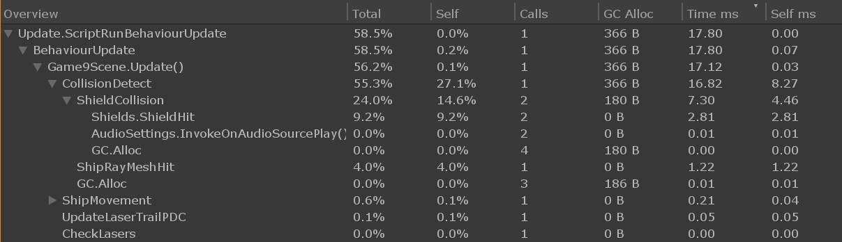
The above image from the profiler shows the frame where the collision happened for the first time in the game, the below image shows the exact same collision after going back to the menu and restarting the same scene.
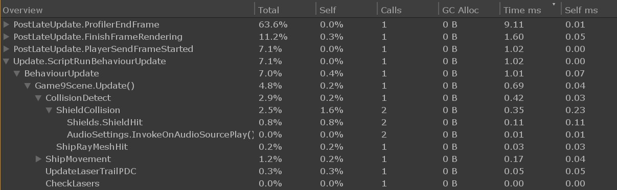
As you can see, the first time the ships collide the CollisionDetect() code takes 16.82ms (much more than a single frame time) to execute, and even allocates 366 bytes of memory. However, the exact same code when executed again takes only 0.42ms and allocates no memory. I had been wondering about those strange memory allocations, as my code should not allocate any memory during the time it runs. Okay, it pretty clearly looks like there is some code compilation going on when the collision code is first run. I could get rid of this by porting that code to native C code, but that would be quite a lot of work. I began to wonder if there would be a way to force Unity to compile this code even before it gets executed?
I found an interesting post called "JIT Methods at runtime", which had a technique for compiling the methods of a class before they get executed. I tested this, but sadly it did not seem to work. It gave no errors, but the methods just took as long to execute as before. Then I googled for something similar with Unity, and that finally gave me the answer I was looking for, from Unity Answers. I changed the inner contents of my code to use this GetFunctionPointer() method, and that finally got rid of the large frame drops when the first collision happens!
I added the following code to each of my main classes (this is from the Ships class, I am sure there is a way to get the type of the owning class inside a static method, but I didn't bother hunting for that). I then added a call to all these methods into my loading scene, and got much nicer framerates in the actual game!
    // Precompile all the methods of this class
    public static void Jit()
    {
        var methods = typeof(Ships).GetMethods(System.Reflection.BindingFlags.DeclaredOnly |
                                               System.Reflection.BindingFlags.NonPublic |
                                               System.Reflection.BindingFlags.Public |
                                               System.Reflection.BindingFlags.Instance |
                                               System.Reflection.BindingFlags.Static);
        foreach (var method in methods)
        {
            method.MethodHandle.GetFunctionPointer();
        }
    }
There are still some slight frame drops when a lot of action happens in the game, but that is as expected, and I can now use the profiler to check the actual method time usage, and not get confused by the weird results of the first call of the method. Any frame drops in a cockpit game are quite distracting (unless they happen during a level change or ship teleport or some such situation where a sudden jump is to be expected). I think I will move more code into native code, as that seems to help quite a lot with various performance issues. I have also tested the IL2CPP backend instead of the default Mono backend, but that does not cause a noticeable difference in the frame rates.
Feb 8th, 2019 - Trailer Released, Oculus Start Dev Kit Arrived
Trailer Released!
Okay, a bit of an unscheduled blog post this time, as I just released the first trailer for my game! Yay! I guess making a trailer while the game is still pretty far from finished was a bit premature, but it began to bother me that I had no proper clips or screen shots to show off my game. I have been working on the nitty gritty details for a long time, which began to make me feel like there is nothing working correctly yet in the game. Thus, to help with my motivation to keep working on the game, I decided to take some time off the actual game development and make a trailer, using stuff that actually does already work. With some clever camera work and editing I was able to hide most of the non-working stuff and focus on getting some pretty clips from the gameplay. The trailer even includes some cheesy voice over lines (special thanks to Tom Doughty for the voice!) and a lot of explosions!
Oculus Start Development Kit Arrived!
As I mentioned in an earlier blog post, I got accepted into the Oculus Start program on the 1st of November last year. I had been waiting for my development kit to arrive since that time, and finally on the 28th of January it arrived! Even though the kit had nothing that I absolutely needed (as I already had an Oculus Rift and the Gear VR device), I wanted to test my game on the Oculus Go device (which the kit also included). Now I can make sure my game runs great also on the Oculus Go, and not just on the Gear VR devices. Here is a picture of the development kit contents (the new Oculus Rift is in the cardboard box underneath all the other stuff).
Also, and completely unrelated to LineWars VR: Happy Birthday to my sister!
Jan 20th, 2019 - Pirate Cockpit Work, Music for LineWars VR, and Other Progress
Happy new year, and welcome to a new blog page! The old page where I had written all the blog posts from 2018 had pretty much overgrown, so I decided to split it into two separate pages, and begin a new blog page for posts from this year.
Pirate Cockpit Work
After writing the previous blog post, I continued working on the Pirate ship cockpit. I needed still to do quite a bit of modeling, and even more texturing. I decided to use the same system as I did with the Cobra cockpit where I have two separate meshes, where the major difference is how they use the common texture atlas. One mesh uses the texture atlas as four separate greyscale textures, which allows me to have very detailed legends for the various switches and instruments. This mesh also uses only sharp edges with no round shapes. Then I have another mesh containing all the round shapes and using the same texture atlas as a normal RGB texture. For the Pirate ship cockpit, I also needed a third mesh for the canopy rim, where I used some volumetric rendering techniques as I described in my previous blog post.
I actually needed to revisit my canopy rim volumetric rendering algorithm, as the idea I had about using just a two-dimensional intersection test was actually flawed. When I moved my head sideways (using the 6DOF Oculus Rift I use for development) the canopy rim shape changed weirdly, so obviously my algorithm was not correct. Instead of trying to fix my algorithm, I decided to check how much of a performance hit I would need to take to use a proper ray-cylinder intersection test. I used the intersection test code based on ��igo Qu�lez's list of primitive intersection tests, which actually turned out to be cheaper than the code I used originally! This intersection test only needs one sqrt operation while my original code had two of those. I was able to simplify the intersection code quite a bit because my cylinder has one cap at the origin and is oriented along the Z axis.
After the canopy rim was fixed, I then alternated between working on the modeling, texturing, and shadow algorithm work for the rest of the cockpit. The shadow algorithms were somewhat more complex because of the round canopy rim, and also because of the bubble canopy. The cockpit will get shadows also from the pilot's helmet, which obviously should not be rectangular. Because the canopy rim is actually slightly angled relative to the instrument panel, it causes the closer shadow plane to actually intersect the instrument panel around the middle of the panel. This meant I had to split all my instrument panel polygons along this intersecting shadow plane, as my shadow algorithms only work when all the vertices of a triangle are on the same side of the shadow plane.
I still haven't implemented quite all shadow planes I would need (for example the back of the ship should also cause shadows on the instrument panel and on the canopy rim when the sun is very low behind the ship), but most of the shadows already work. The CanopyRim fragment shader (using volumetric rendering and self-shadowing, along with shadows from the pilot's helmet and from the horizontal rim of the cockpit) has performance characteristics like this:
  4 work registers used, 1 uniform registers used, spilling not used.

                          A       L/S     T       Bound
  Instructions Emitted:   33      3       1       A
  Shortest Path Cycles:   1.5     1       0       A
  Longest Path Cycles:    12      3       1       A
So, not quite under the 10 GPU cycles I am aiming at, but as my GPU cycle budget is at up to 20 GPU cycles per fragment,
I am still well within that budget. Sadly, this will still get slightly slower when I add the missing shadows. On the other
hand, the canopy rim is not very big on the screen, so that helps somewhat.
The current performance of the main Pirate cockpit fragment shader is as follows:
  4 work registers used, 1 uniform registers used, spilling not used.

                          A       L/S     T       Bound
  Instructions Emitted:   32      7       1       A
  Shortest Path Cycles:   2.5     2       1       A
  Longest Path Cycles:    10.5    7       1       A
This too is slightly over the 10 GPU cycles, and it also is missing the shadow from the rear of the ship.
Currently my pirate ship cockpit is at a sort of passable level as far as stuff in front of the pilot is considered. Anything behind the pilot is still quite unfinished, which is also the case with the older Cobra cockpit and the Cruiser bridge. I will next switch to working on some other missing aspects of my game before then doing a new pass over all of my cockpits at some later time. Here below is an animated GIF image showing the current state of the cockpit, along with some dynamic procedural shadows. The round shadow is caused by the helmet of the pilot. I had to make this GIF image greyscale, to get rid of the very bad color banding. That is a normal issue with GIF images, as they can only contain 256 distinct color values.
Music for LineWars VR
In the beginning of this year I thought it might be a good time to finally get some background music for LineWars VR. Back in June of last year I had gotten an offer by freesound.org user AlienXXX for some music, but sadly (for me) he got a new job and became very busy, so that offer sort of fell through. Since that time, I have been very busy with other aspects of my game, so hadn't thought about the music issue. Now I began to think that perhaps I should start hunting for some music. I first checked the good free music site incompetech which I had used in the past for various YouTube videos. I found a couple of pretty good tracks, but nothing that would really cause a "wow!" effect. I was not very aware of other royalty-free music sites, so I asked for help on the Oculus Start discord channel.
I was recommended a site called AudioJungle. The tracks there are not free, but still reasonably priced and royalty-free. I knew I wanted something rather epic-sounding, so I used search terms like "Epic" and "Cinematic" and the like. These pointed me to a category called "Dramatic, Action & Adventure", which I thought was just what I was after. But there were 48,273 tracks in that category! How could I find just the right tracks for me! Luckily there was a search filter called "looped" which I could use, to look for tracks that have parts suitable for looping, which I would need for my background. But there were still over 2400 tracks to choose from!
After I had downloaded preview files for about 10 different tracks, some quite good, I encountered a track called "Epic Adventure Dubstep Trailer". The track was rather weird, but I decided to download the preview anyway. It was an interesting track, though too weird and also too slow for my purposes. I then continued previewing more tracks, until I had found about 30 or 40 pretty neat tracks. However, I noticed I always came back to replaying that weird Dubstep track by Agroglyph and finding I liked it better than any of the other tracks. I decided to contact him, to ask if he could perhaps make a faster version of that track for my game.
We emailed back and forth, until he offered to actually compose new tracks for all my missions, for a price I can afford! That was a good solution for me, as I could get tracks with similar style for all my missions, and could have a say in how the tracks would be structured and instrumented! I believe that is money well spent, as music is an important part of the gaming experience. I had tested my game with some faster preview tracks I had found, and the game felt like a totally different much more polished game with some good music playing in the background!
As I write this, I have already received a preliminary version of the first new track he will be composing for my game, and even that preview version already works very well. I am quite happy to have gotten the music for my game sorted!
Missions 1 to 4 playable!
As I now got background music coming for all of my nine missions, I thought that perhaps I should start actually implementing more of my missions! Until now I had only implemented a mission that I needed for testing some feature (like Mission 3 for testing the Cruiser PDC stuff and teleporting between different ship types). Since I already had missions 1 and 3 running, it was logical to next work on mission 2. This is the "First Blood" mission, where for the first time the player gets to shoot at other ships and also gets shot at. This is a rather simple mission, so it only took around a day to build it, as everything the mission needed was pretty much implemented already. Just change the skybox, some spawn locations and the narration file in the beginning of the mission.
After I got mission 2 done, it was time to work on mission 4. This is called "Pirate Ambush", and it happens inside a dark asteroid field. At first, I thought I will need some help with creating a skybox that would show the asteroid field, but then I decided to try to tackle this one myself. I took my Asteroid object (which is actually just a sphere) with the procedural textures in Cinema 4D, and used an FFD deformer to make it have a more interesting shape. Then I began experimenting with the Array modeling object of Cinema 4D. I created three arrays of different sized asteroids and in different orientations, and then finally put all of these three arrays into another array. The inside arrays have 8 large asteroids, 21 medium-sized and 59 small asteroids, and the overall array creates 7 copies of these three arrays, for a total of 7*(8+21+59) = 616 asteroids in my asteroid field.
I decided to experiment with a Red Dwarf as the star illuminating this asteroid field, using a very deep red color for the sunlight. I think this created a suitably dark feel for this asteroid field. The great thing about my creating the asteroid field skybox using the same object as what I use for the actual in-game asteroids was that you will have a hard time telling the difference between asteroids in the skybox and the real asteroids. In the screen copy below there are 30 real asteroids visible, all the rest are just part of the skybox. Can you spot the real asteroids?
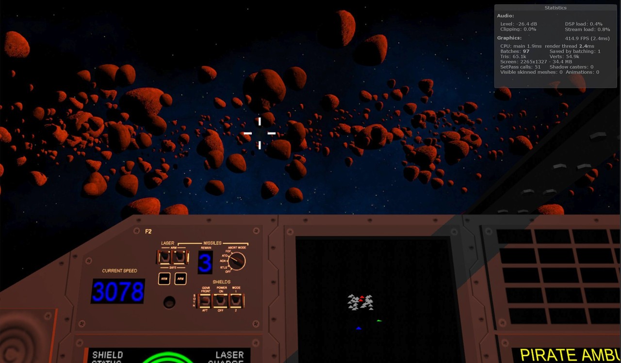
This mission became very entertaining, it is great fun flying between the asteroids chasing and shooting at the enemy ships, while trying to avoid collisions with the asteroids!
Simulated Dynamic Global Illumination
After I had been playing the fourth mission with the very red sunlight for a while, it began to bother me how the illuminated cockpit areas have a very reddish tint, but the areas that are in shadow have no reddish tint at all. In real life the red light would get reflected from the illuminated areas to the cockpit areas in shadow, giving them a red tint as well. This is often called Global Illumination in 3D graphics.
Performing proper accurate Global Illumination would not be possible in real time, but it occurred to me that perhaps I could fake this rather cheaply. I already had a _SunColor uniform vector (with RGBA values) in my cockpit shaders, however the A channel of this vector was not used. I also thought that I could estimate the amount of light getting into the cockpit simply by using my cockpit window shadow planes (as described in my May 20th, 2018 blog post, with the shadow plane image from that blog post copied below). If I used the dot product between the normals of these shadow planes and the sun direction, I should get a quite nice estimate of the amount of light entering the cockpit.
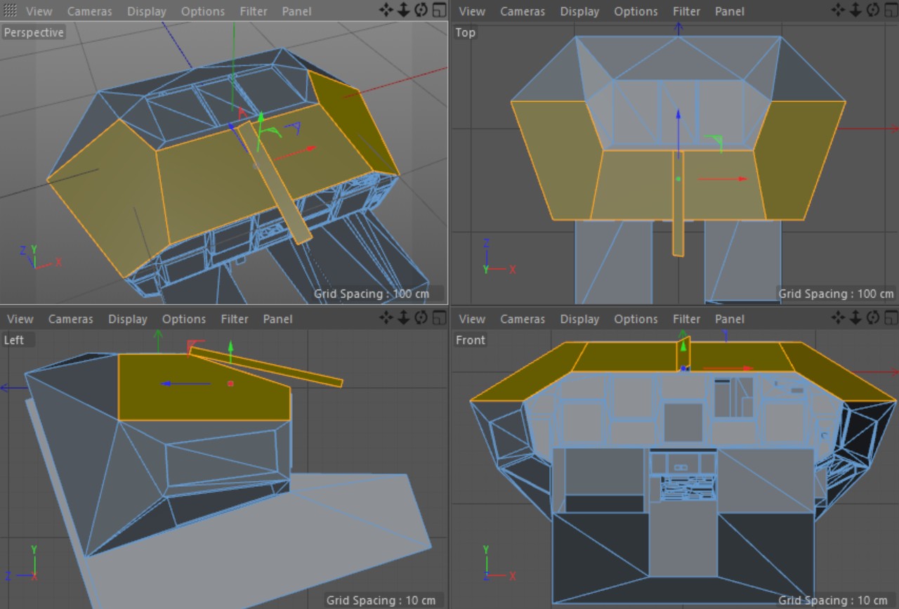
I added code into my cockpit fragment shader to multiply the _SunColor RGB values with the _SunColor.a value and add that to the color of the fragment (both when it is in shadow and when it is lit). I then added code to my C# script to calculate the sum of the dot products for all three shadow planes (the sign is reversed in the code below, because my light vector goes from light towards the cockpit, while the shadow plane normals point away from the cockpit). I then multiply this with a Global Illumination Intensity factor 0.1f (an experimental value for now), and put it into the fourth component of the _SunColor vector.
   float d1 = Vector3.Dot(lightDir, cobra_N1);
   float d2 = Vector3.Dot(lightDir, cobra_N2);
   float d3 = Vector3.Dot(lightDir, cobra_N3);
   float gi = 0f;
   if (d1 < 0)
       gi += -d1;
   if (d2 < 0)
       gi += -d2;
   if (d3 < 0)
       gi += -d3;
   // Setup the sun color, including simulated global illumination.
   Vector4 sunColGI = Movement.SunColor * 6.0f * Movement.ShadowMult;
   sunColGI.w = 0.1f * gi;
   Shader.SetGlobalVector("_SunColor", sunColGI);
If you are wondering what those multipliers of 6.0f and Movement.ShadowMult are, the first is just a global brightness factor (so that I can have non-white sun colors without lessening the sun brightness), and the second one gets zeroed if the cockpit is in the shadow of some other object, like an asteroid or another ship.
This worked reasonably well, but did not take into account any Ambient Occlusion, that is, parts of the cockpit that would not receive much indirect light. At first, I thought this will be a problem I cannot cheaply solve, until I realized that I already have Ambient Occlusion emulation for the ceiling light! This is handled by having a multiplier for each vertex telling how much the ceiling light illuminates that vertex. Since the Global Illumination is not directly related to the Ceiling Light intensity, I could not use the value directly. However, I thought that if I simply decrease the global illumination intensity for those vertices that also have very little illumination from the ceiling light (like the foot wells), the end result might be pretty close to what I want. Thus, I added the following code to my fragment shader:
    // i.lightData.x contains the ceiling light multiplier for the vertex
    fixed4 shCol = tmp > 0.5 ? col : col * i.lightData.x + oculusdither(i.vertex.xy) + tmp * _SunColor * min(_SunColor.a, i.lightData.x);
That is, I multiply the sun color with the minimum of the Global Illumination Intensity from _SunColor.a
and the Ceiling Light intensity from i.lightData.x. The tmp value is the (greyscale) color from my
cockpit texture.
The cost of this change in the shader was only 0.5 GPU cycles, as the fragment shader cycle count went from 8 to 8.5 after this change. The image below shows a comparison shot with and without this Global Illumination emulation. I think the result is worth the very minor performance hit.
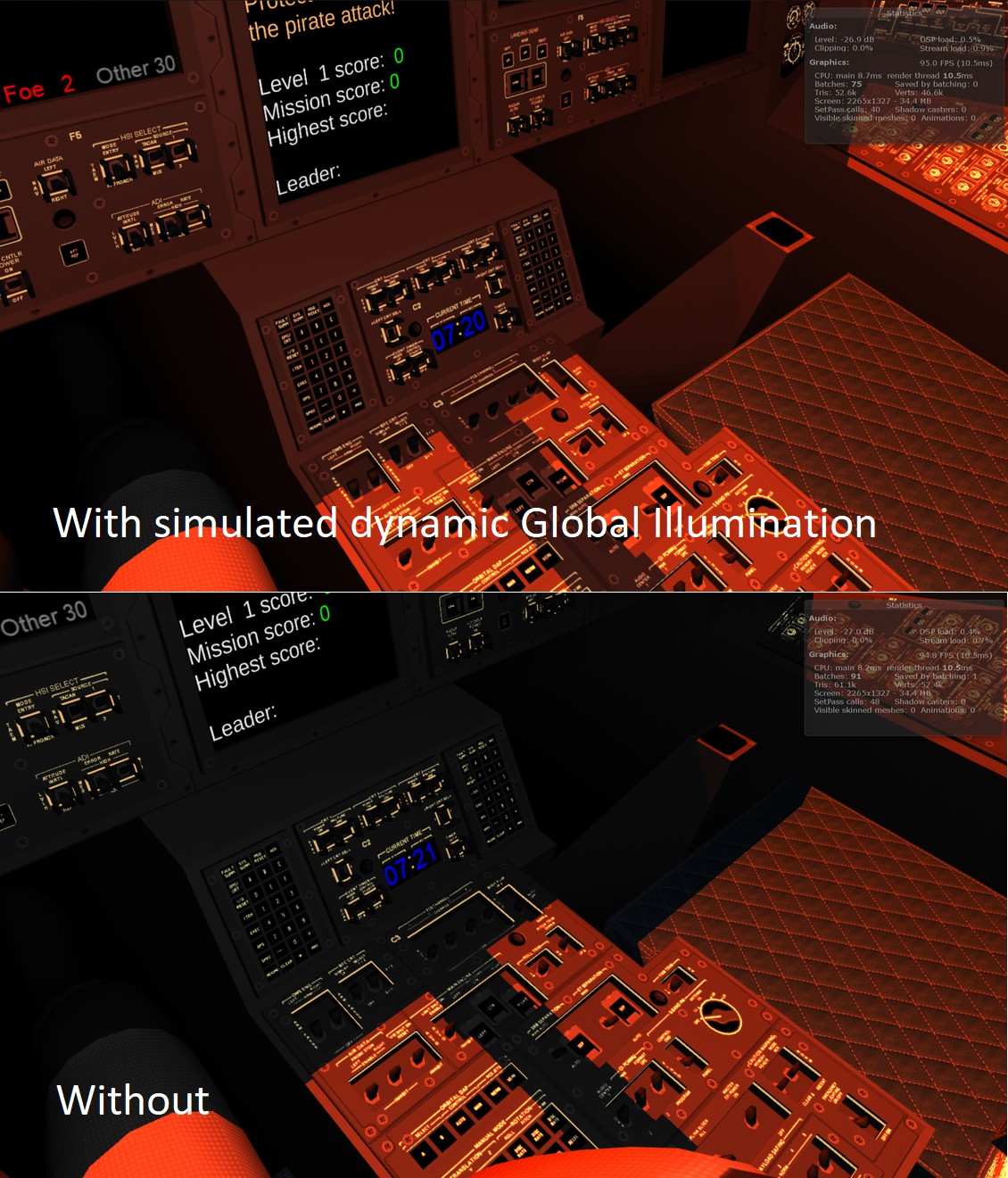
I decided to also make a short video from the Mission 4 I mentioned above. My old pre-alpha gameplay video had gotten rather old already, as it didn't have the trails from the ships, the new more visible lasers, or any music. This new alpha gameplay video should more closely reflect the current state of the game.
That's about it for this blog post, thanks again for your interest in my blog and LineWars VR!
Previous blog posts
See here for blog posts from 2018 and before.