
LineWars VR Blog Posts
Dec 24th, 2018 - Native Code Plugin, Engine Thrust Trails and Volumetric Rendering
Merry Xmas! For the past month I have been working on three new features; I converted the PDC bullet handling to native code, added some thrust trails to my fighter ships and missiles, and also experimented with some volumetric rendering. Before I tackled these things, though, I continued with the Cruiser damage textures.
By the time I wrote the previous blog post, I had not yet handled the lighting changes that result from a hit that kills a floodlight illuminating a part of the cruiser body. There are flood lights shining on each of the eight PDC platforms, and also eight floodlights (four pairs) illuminating the shuttle landing platform. I coded a system where a hit to the panel containing such a light switches the illuminated textures to non-illuminated versions. This looks pretty good, though the effect is rather subtle. Many players will probably never even encounter this effect in the game.
Native Code Plugin
After I got my work on the Cruiser damage textures finally completed, I was quite bored and fed up with working on the texture stuff, and wanted to do something interesting (like proper coding!) for a change. I had wanted to learn how to create a native plugin for Android in Unity, so I decided to finally take some time and look into this. The first step was to install Android NDK, which was quite simple to do, following a guide I found from Stack overflow. I did not want to install the full Android Studio, so I used just the command line tools. I did have some trouble getting my native test code to work, but these problems were mainly caused by some silly things. I first tried to use a static library (.a), but that did not seem to work, so I switched to a shared library (.so). Then I forgot to mark my functions as extern. After fixing a few issues like these, I finally was able to call a simple test plugin without issues.
I then began porting the PDC bullet movement code to my new native plugin. The first step was to port the C# code (which actually is based on my compute shader experiment shader language code) to plain C language. I tested using the Unity stopwatch how much time my C# code and my simple C code took when moving all 384 bullets and doing the collision tests. The C# code took 18000 ticks, while the naive unoptimized C code took 1300 ticks! So, there was an order of magnitude improvement just by switching from C# to C language!
Encouraged by the results, I decided to port the code all the way to NEON ASM. Curiously, my first NEON ASM implementation was slower than the C version, it took 2300 ticks to move the bullets! After some studying, I realized that I was mixing NEON and VFP float opcodes, which stalls the pipelines and pretty much kills the performance. I fixed this problem, and got the code to run at around 700 ticks, but it was still somewhat less optimized than I wanted. I decided to let it be for now, and get back to it at some later time.
The C# side of my native plugin API looks like this:
    [DllImport("NativePlugin")]
    private static extern void SetupBuffers(IntPtr vertexBuffer, IntPtr hitBuffer, IntPtr newBuffer);

    [DllImport("NativePlugin")]
    private static extern void UpdateVertices(float camX, float camY, float camZ);

    private static Mesh ltMesh;
    private static Vector3[] ltvertices;

    private static GCHandle vertArrayHandle;
    private static GCHandle hitArrayHandle;
    private static GCHandle newArrayHandle;

    // Send the addresses of our static vertex, hit buffer and new bullet arrays to the native code.
    public static void SetupPDCPlugin(Vector3[] verts, Vector4[] hitBuf, Vector4[] newBuf)
    {
        if (!vertArrayHandle.IsAllocated)
            vertArrayHandle = GCHandle.Alloc(verts, GCHandleType.Pinned);
        if (!hitArrayHandle.IsAllocated)
            hitArrayHandle = GCHandle.Alloc(hitBuf, GCHandleType.Pinned);
        if (!newArrayHandle.IsAllocated)
            newArrayHandle = GCHandle.Alloc(newBuf, GCHandleType.Pinned);
        SetupBuffers(vertArrayHandle.AddrOfPinnedObject(), hitArrayHandle.AddrOfPinnedObject(), newArrayHandle.AddrOfPinnedObject() );
    }

    ...

        SetupPDCPlugin(ltvertices, hitBuffer, newBullets);

    ...

        // Call native code to handle all the vertex updates.
        UpdateVertices(cameraPos.x, cameraPos.y, cameraPos.z);
        ltMesh.vertices = ltvertices;

    ...
The corresponding C code in my native plugin looks like the following. This is basically just a wrapper over the NEON ASM
routine that does the actual bullet movement and hit test handling. I use this C wrapper to make it easier to handle
pointers to variables, otherwise I would need to do some position-independent code trickery in my ASM code to make this work.
The C compiler does all this for me, so I don't need to worry about it.
#define	BULLETCOUNT 384

// Structure for PDC bullets
struct PDCDataStruct
{
    float    pos[3];    // Position of the bullet
    float    age;       // Age of the bullet, inactive when == 0
    float    dir[3];    // Direction of the bullet
    float    act;       // Activity flag, 0 == inactive, -1.0 == active
};

static float* vertBuf = 0;
static float* hitBuf = 0;
static float* newBuf = 0;
static int freePDCidx = 0;          // Index of the next free PDC bullet
static struct PDCDataStruct dataBuffer[BULLETCOUNT+8];	// Buffer for the bullet data

extern void MovePDCBulletsASM(float camx, float camy, float camz, float *vertBuf, float *hitBuf, float *newBuf, int *freeIdxAdr, struct PDCDataStruct *dataBuffer);

// Remember the buffer pointers, given from the C# side
extern void SetupBuffers(void *vertData, void *hitData, void *newData)
{
    vertBuf = (float *)vertData; // Global vertex buffer
    hitBuf = (float *)hitData;   // PDC hit buffer
    newBuf = (float *)newData;   // PDC new bullets buffer
}

// Update the global vertex buffer contents
extern void UpdateVertices(float camX, float camY, float camZ)
{
    //----
    // Move the PDC bullets
    //----
    MovePDCBulletsASM(camX, camY, camZ, vertBuf, hitBuf, newBuf, &freePDCidx, dataBuffer);
}
The NEON ASM code basically consists of four separate sections: Creating new bullets, moving the bullets, testing for bullet hits, and creating vertices for the bullets. The first section is a separate loop, and the other three sections are within the main loop that handles each bullet separately. Creating new bullets is pretty simple, the ASM code receives a pointer to an array of new bullets, with the array items having the same PDCDataStruct format as the actual dataBuffer items. Whenever a new bullet needs to be created, the act flag of the item in the new bullet buffer is -1.0. New bullets are created at slot freePDCidx, which goes around the dataBuffer in a round robin fashion.
The full ASM code for moving the bullets is a bit too long to write out here completely, so I'll show various interesting bits and pieces of it instead. The dataBuffer items contain the current position of the bullet, the bullet's age, and the direction where the bullet is moving. The direction vector is not a unit vector, instead it also contains the speed of the bullet. As the last item of the item is -1.0, it is easy to both move the bullet and decrement the age using a single NEON ASM vadd operation:
    //----
    // This is an active PDC bullet. Handle it.
    // Add direction to pos and -1 to age
    //----
    vldmia          r10, {q10-q11}        // Load databuffer values, q10 = pos, q11 = dir
    vadd.f32        q10, q11              // pos = pos + dir, age = age - 1
After the bullets have been moved, it is time to test if the bullet hits something. A full test for every bullet against
every single moving ship would be prohibitively expensive performance-wise, so I use a system where I precalculate the
eight closest ships (or asteroids) to the cruiser. The collision tests are only done against these eight closest objects,
and the hit test uses only the ship's shield radius (or the asteroid's radius) to determine whether there was a hit.
Each hit buffer item consists of two sets of four floats, the first set contains the ship's position and shield radius
(squared), and the second set of four floats is initially zero, and gets set to the hit position (to be able to show the
shield flash starting from the correct position) and a flag that tells there was a hit.
Here below is a macro that checks hits of a bullet against two hitBuffer items in one go (as using interleaved registers is faster than using the output register of the previous operation as input to the next operation). This macro also clears the bullet's age if there was a hit. This code does some bit masking trickery so that I don't need to do any conditional jumps, as those would need setting the CPU flags, which can only be done using the VFP instructions, which stall the NEON pipeline. Thus, this code saves all the hitBuffer values every time, even though it would only need to save the second set of four floats and only if there was a hit. I believe it is still faster to do it this way than using the VFP instructions and conditional jumps.
.macro HIT_TEST
    //----
    // Check bullet hit against two hitBuf slots.
    // Input registers:
    //  r6 = hitBuf slot address
    //  q9 = mask for clearing the highest float of a Q register
    //  q10 = bullet position
    // output registers:
    //  r6 = points to 2 hitBuf slots after the initial r6 value
    //  q10 = bullet position, highest float (== age) cleared if a bullet hit
    // Clobbered registers:
    //  q0-q6
    //----
    vldmia          r6, {q0-q3}           // Load 2 times hitBuf[j] pos and shieldRadius*shieldRadius and hitBuf[j+1] = hit position and flag
    vsub.f32        q4, q10, q0           // q4 = p = pos - hitBuf[j] (first hitbuf slot)
    vsub.f32        q5, q10, q2           // q5 = p = pos - hitBuf[j] (second hitbuf slot)
    vand            q4, q9                // q4 = px, py, pz, 0.0 (1st)
    vand            q5, q9                // q5 = px, py, pz, 0.0 (2nd)
    vmul.f32        q4, q4, q4            // q4 = px*px, py*py, pz*pz, 0.0 (1st)
    vmul.f32        q5, q5, q5            // q5 = px*px, py*py, pz*pz, 0.0 (2nd)
    vpadd.f32       d8, d8, d9            // d8 = px*px+py*py, pz*pz+0.0 (1st)
    vpadd.f32       d10, d10, d11         // d10 = px*px+py*py, pz*pz+0.0 (2nd)
    vpadd.f32       d9, d8, d8            // d9 = px*px+py*py+pz*pz, px*px+py*py+pz*pz (1st)
    vpadd.f32       d11, d10, d10         // d11 = px*px+py*py+pz*pz, px*px+py*py+pz*pz (2nd)
    vclt.f32        q4, q4, q0            // Is px*px+py*py+pz*pz < shieldRadius*shieldRadius? (highest float = 0 / 0xFFFFFFFF) (1st)
    vclt.f32        q5, q5, q2            // Is px*px+py*py+pz*pz < shieldRadius*shieldRadius ? (highest float = 0 / 0xFFFFFFFF) (2nd)
    vdup.f32        q4, d9[1]             // q4 = [ 0 / 0xFFFFFFFF, 0 / 0xFFFFFFFF, 0 / 0xFFFFFFFF, 0 / 0xFFFFFFFF ] (1st)
    vdup.f32        q5, d11[1]            // q5 = [ 0 / 0xFFFFFFFF, 0 / 0xFFFFFFFF, 0 / 0xFFFFFFFF, 0 / 0xFFFFFFFF ] (2nd)
    vbic            q1, q4                // q1 = 0 (if 1st bullet hit) or previous 1st bullet hit value (if 1st bullet did not hit)
    vbic            q3, q5                // q3 = 0 (if 2nd bullet hit) or previous 2nd bullet hit value (if 2nd bullet did not hit)
    vand            q6, q10, q4           // q6 = [ pos.x, pos.y, pos.z, age ] (if 1st bullet hit) or 0 (if 1st bullet did not hit)
    vorr            d9, d11               // d9 = all bits set if either hitBuf slot was a hit, else 0
    vand            q5, q10, q5           // q5 = [ pos.x, pos.y, pos.z, age ] (if 2nd bullet hit) or 0 (if 2nd bullet did not hit)
    vorr            q1, q6                // q1 = hit position (if 1st bullet hit) or original value (if 1st bullet did not hit)
    vbic            d9, d19               // d9 = [ 0, 0 / 0xFFFFFFFF ] (highest float all bits set if either hitBuf slot was a hit)
    vorr            q3, q5                // q3 = hit position (if 2nd bullet hit) or original value (if 2nd bullet did not hit)
    vbic            d21, d9               // pos.age = 0, if the bullet hit either of the hitBuf slot ships
    vstmia          r6!, {q0-q3}          // Save two slots of hitBuf values, point r6 to next slot
.endm
What remains is the creation of the vertices based on the bullet position. I use just 4 vertices per bullet, with two triangles, the forward triangle and the tail triangle. I need to orient the triangles so that they face the camera, and I also decided to adjust the bullet size based on the distance of the bullet to the camera. This way the far away bullets are more visible, and bullet trails very close to the camera do not look unnaturally large. This meant calculating a cross product between the bullet direction vector and the camera-to-bullet vector, and calculating the length of both this side vector, and the length of the camera-to-bullet vector. The ARM Neon Programmers Guide chapter 7: NEON Code Examples with Mixed Operations contains a neat algorithm for calculating a cross product between two vectors using NEON ASM, so I used that algorithm for the cross-product calculation.
After the cross-product vector was ready in the q0 register, it was time to calculate the lengths of these vectors. The camera-bullet vector is in the q4 register at the start of the following code snippet. I first calculate the dot products of these vectors (squaring the vector elements, and then using vpadd to add these elements together). Then I use the vrsqrte (Vector Reciprocal Square Root Estimate) operation to find the 1/sqrt() values for both of these vectors in one go. Then I duplicate these values to the q2 and q3 registers, to be able to multiply the original vectors with these values. I then multiply the bullet distance scaling factor (in register d16, currently 2401.0) with the bullet distance, take its reciprocal value using the vrecpe operation, and add the bullet size (from register d17) to this value. This will then be used to multiply the bullet front and side vectors, to get the resulting bullet vertices.
    //----
    // Calculate the lengths of the two vectors:
    //  q2 (d4 low) = 1/(camera-bullet) vector length
    //  q3 (d4 high) = 1/cross product length
    // Remember the distance to camera for bullet size adjust.
    //----
    vmul.f32        q2, q4, q4            // q2 = [ distx*distx, disty*disty, distz*distz, 0.0 ]
    vmul.f32        q3, q0, q0            // q3 = [ crossx*crossx, crossy*crossy, crossz*crossz, 0.0 ]
    vpadd.f32       d4, d4, d5            // d4 = [ distx*distx+disty*disty+distz*distz, 0.0 ]
    vpadd.f32       d6, d6, d7            // d6 = [ crossx*crossx+crossy*crossy, crossz*crossz+0.0 ]
    vpadd.f32       d4, d4, d4            // d4 = [ distx*distx+disty*disty+distz*distz, distx*distx+disty*disty+distz*distz ]
    vpadd.f32       d6, d6, d6            // d6 = [ crossx*crossx+crossy*crossy+crossz*crossz, crossx*crossx+crossy*crossy+crossz*crossz ]
    vzip.32         d4, d6                // d4 = [ distx*distx+disty*disty+distz*distz, crossx*crossx+crossy*crossy+crossz*crossz ]
    vrsqrte.f32     d4, d4                // d4 = [ 1/sqrt(distx*distx+disty*disty+distz*distz), 1/sqrt(crossx*crossx+crossy*crossy+crossz*crossz) ]
    vdup.32         q3, d4[1]             // q3 = [ 1/crosslength, 1/crosslength, 1/crosslength, 1/crosslength ]
    vdup.32         q2, d4[0]             // q2 = [ 1/distlength, 1/distlength, 1/distlength, 1/distlength ]
    vmul.f32        q0, q3                // q0 = side = Cross(camera - pos, dir).normalized
    vmul.f32        d12, d5, d16          // d12 = [ 2401.0/distlength, 2401.0/distlength ]
    //----
    // float size = BULLETSIZE + (camera - bullet).magnitude / BULLETDIST;
    //----
    vrecpe.f32      d12, d12              // d12 = [ distlength/2401.0, distlength/2401.0 ]
    vadd.f32        d12, d12, d17         // d12 = [ BULLETSIZE + distlength/2401.0, BULLETSIZE + distlength/2401.0 ]
    vmov.f32        q4, #4.0              // q4 = [ 4.0, 4.0, 4.0, 4.0 ]
    vdup.32         q6, d12[0]            // q6 = [ size, size, size, size ]
    //----
    // Calculate the final side and dir vectors
    //----
    vmul.f32        q5, q11, q6            // q5 = [ dirx*size, diry*size, dirz*size, 0 ]
    vmul.f32        q6, q0, q6             // q6 = [ sidex*size, sidey*size, sidez*size, 0 ]
    vmul.f32        q4, q5                 // q4 = [ dirx*4*size, diry*4*size, dirz*4*size, 0 ]
The final steps are then to add the calculated direction*size and side*size vectors to the actual bullet position, and save the vertices to the vertex array. The problem here is, that the NEON registers are sort of Vector4 type, while the vertex array has Vector3 values. So, I need to convert from 4*4 floats down to 4*3 floats. Luckily 4*3 is the same as 3*4, so I can save four vertices using 3 NEON registers. It requires some shifting of the separate coordinates to their correct positions in the NEON registers to be able to do the saving with a single vstmia instruction. I would like to have used the vst3.32 interleaved save instruction, but I could not figure out how to use that properly in this situation. I'll revisit this code, if and when I figure that out.
    //----
    // Calculate the vertex positions.
    //  q10 = position of the bullet
    //----
    vadd.f32        q0, q10, q5           // q0 = [ posx+dirx*size, posy+diry*size, posz+dirz*size, 0 ]
    vadd.f32        q1, q10, q6           // q1 = [ posx+sidex*size, posy+sidey*size, posz+sidez*size, 0 ]
    vsub.f32        q2, q10, q6           // q2 = [ posx-sidex*size, posy-sidey*size, posz-sidez*size, 0 ]
    vsub.f32        q3, q10, q4           // q3 = [ posx-dirx*4*size, posy-diry*4*size, posz-dirz*4*size, 0 ]
    //----
    // Build the vertices into q0..q2
    //----
    vrev64.32       d13, d5               // q6 = [ ???, ???, 0.0, v2z ]
    vext.8          q0, q0, q0, #12       // q0 = [ 0.0, v0x, v0y, v0z ]
    vext.8          q0, q0, q1, #4        // q0 = [ v0x, v0y, v0z, v1x ] = OK
    vext.8          q1, q1, q1, #4        // q1 = [ v1y, v1z, 0.0, v1x ]
    vmov            d3, d4                // q1 = [ v1y, v1z, v2x, v2y ] = OK
    vext.8          q2, q6, q3, #12       // q2 = [ v2z, v3x, v3y, v3z ] = OK
    //----
    // Save the vertices, from q0..q2
    //----
    vstmia          r3, {q0-q2}           // Save 3*4 == 4*3 floats to vertBuffer
Engine Thrust Trails
After I got the PDC bullets working using native code, I thought that perhaps I could use the same native code to also add some engine thrust trails to my game! I have always felt that such trails are a bit of an overused element in space games, but I wanted to see what they would look like. I hadn't bothered to experiment with the Unity built-in Trail Renderer, as I am not sure how efficient that is. I thought that the Trail Renderer might even need a separate GameObject for every separate trail, which would be very inefficient. Instead, I thought I could extend my single object that contains all the PDC bullets to also contain the vertices for all the thrust trails I would need.
I began my experiments using some C# code to generate additional vertices to my PDC bullet object, and noticed that with 16 segments per trail, and each segment consisting of 3 vertices, I could get quite smooth trails. I decided to allocate a table of 64 trails (so in total 64*16*3 = 3072 vertices), and added trails for each of my fighter ships, one trail for the single-engine Pirate fighter, and twin tails for the two-engine Cobra fighters. Those 64 trails will still have a few trails free for use for missiles as well. I uploaded an image (below) of the trails to the Oculus Start Member forum, asking whether such trails are overused. The response was quite clear, trails are not overused, instead, they are very useful and almost required for such space games! Okay, consider me convinced. :-)
After I got the C# code working, I ported also this code to NEON ASM, to have it cause as little a performance hit as possible. The way I move my trails is that the first segment of the trail (the first three vertices) are updated every frame, but the remaining vertices are only updated every four frames. During this every-fourth-frame update I rotate the segments to face towards the camera, and take the current position of the previous segment for each segment of the trail. This way I don't need to update the vertex colors at all. When the ship is destroyed, this also nicely fades out the trail, until the last segment position is equal to the first segment position, at which point I can mark this whole trail as inactive.
After my PDC bullets and trails were using NEON ASM, I decided to also port my laser rod handling to NEON ASM. My lasers had been using the Unity Line Renderer, so each of them was a separate GameObject. I hadn't been able to create a nice material for the lasers, and they did not adjust to the distance to camera, both of which I was able to fix when I switched over to the NEON ASM code. Now also the lasers scale by their distance. I am using 8 vertices per laser rod, so that I can have the center being yellow, and then have a gradual fade to dark red towards the laser rod outer rim. This change got rid of yet another set of GameObjects and thus draw calls, so the performance of my game is now better than it was originally! The new NEON ASM code runs between 200 and 700 ticks per frame, depending on the number of bullets, trails and lasers active.
Volumetric Rendering
After having fun with the NEON ASM code for a while, it was time to get back to modeling, this time for the Pirate fighter cockpit. I want the Pirate ship to have a bubble canopy, but I could not make the canopy rim look perfectly round without going to a huge number of polygons and vertices. After a while fighting with this, I decided to look for a different technique. I had some time prior to this encountered a series of "Volumetric Rendering in Unity" tutorials by Alan Zucconi, which are based on some earlier articles by the graphics rendering guru ��igo Qu�lez.
Volumetric rendering is nowadays most often used for rendering clouds or various other non-solid things, but it can be used just as well for solid objects. The most common technique for volumetric rendering uses "raymarching" to probe a cubic volume containing the shape we are interested in, to determine where the view ray hits the surface. The problem with this approach is that the raymarching usually needs to "march" many steps before it hits the surface. However, if you know the formula of the surface, you can use a ray intersection test to determine where the surface lies for each view ray in a single step. This method is not without its own problems, as the intersection test can get very complex very quickly, which makes this method unsuitable for anything but the most primitive shapes. Luckily, the shape I was after was a simple cylinder, with the inner radius of 0.4 meters and outer radius of 0.45 meters, and the closer end cap at Z=0 coordinate. This sounded like a good candidate for volumetric rendering using the analytical approach based on the cylinder formula x2 + y2 = r2.
I added a simple Quad primitive to my scene where I wanted the canopy rim Z=0 position to be, and began working on the fragment shader. The first step was to clip() all fragments that do not belong to this canopy rim. The end cap of my half-cylinder was easy to handle. I just needed to send the object-space coordinates from the vertex shader to the fragment shader, and then clip the outer area:
    float outerR = dot(i.pos.xy, i.pos.xy);     // outerR = x2 + y2
    if (outerR > 0.45*0.45)                     // If outerR > r2, the fragment should be ignored.
    {
        clip(-1);
        return 1.0;
    }
The code for the inner part of the canopy rim is a bit more involved, as I needed to have the surface of the cylinder
at 0.4 meters radius, with a depth of 12 cm (or 0.12 meters) for the rim. I thought that it would be easiest to handle
by projecting the view ray to the backside end cap, and test if the end cap hit position is more or less than 0.4
meters from the center. If it is more, this fragment is on the inside of the canopy rim, else the fragment needs to be
discarded:
    if (outerR < 0.4*0.4)	// x2 + y2 < 0.42, so this fragments is not part of the closer end cap.
    {
        // This fragment could be on the inside rim area
        float3 viewDir = normalize(i.pos.xyz - i.cam);  // Vector from camera to the fragment.
        float2 backPos = i.pos.xy + 0.12 * viewDir.xy;  // Fragment position projected on the back end cap.
        float innerR = dot(backPos, backPos);
        if (innerR < 0.4*0.4)
        {
            // Inside the inner rim, so this fragment should not be visible at all.
            clip(-1);
            return 1.0;
        }
Okay, so far this has been pretty straightforward. Now comes the tricky part, how do we calculate the actual fragment
position on the inner cylinder of the canopy rim, which we will need for the lighting and shadow calculations? Normally
this would mean solving a quadratic function based on the cylinder equation, however, since we already know the hit
positions on the closer end cap and on the back-end cap, we can simplify this problem into the intersection point of
two lines. Furthermore, as we know this point will lie on the inner surface of the cylinder, we can simplify this line
intersection problem to two dimensions:
        // Determine the intersection point on the canopy rim inside cylinder.
        // Simplify this to two dimensions, using sqrt(x2+y2) as the first axis, and z as the second axis.
        float2 front = float2(sqrt(outerR), 0);
        float2 back = float2(sqrt(innerR), 0.12);
        // Find the Z-coordinate of the cylinder intersection point.
        float z = 0 + (0.4 - front.x) * (0.12 - 0) / (back.x - front.x);
        // Get the full X,Y,Z position of this intersection point.
        float3 innerPos = float3(i.pos.xy + z * viewDir.xy, z);
        if (innerPos.y < 0)
        {
            // Below the lower edge of the rim, so not visible.
            clip(-1);
            return 1.0;
        }
Since the quad we are using for creating the virtual 3D object has no depth, we need to manually discard the
fragments that would be underneath the y=0 line "inside" the virtual volume. Otherwise those would be projected
onto the quad surface (just like viewing the object through a window), which is not what we want.
Here below is an animated GIF image showing the resulting object, including some procedural self-shadowing.
The self-shadowing was easy to add, as we can use the same formula we used for the view vector, but this time
using the light vector, to determine whether the fragment is in shadow or not.
Please ignore the messed-up textures in the low part of the cockpit, and the quantized colors caused by the GIF
format.
Next, I will need to continue working on the other part of the Pirate cockpit, and I will need to add proper shadow handling to that cockpit as well. This may be somewhat trickier due to the bubble canopy, but I do have some ideas about how to handle this efficiently.
This blog page has grown to be quite lengthy, so I will add a new page when I add my first blog post of next year. Have a Merry Xmas and a Happy New Year, and thank you for your interest in my blog posts and in my LineWars VR game!
Nov 24th, 2018 - Progress on Multiple Fronts, Oculus Start Program
Happy one-year anniversary of LineWars VR! Tomorrow it will be exactly one year since I started this project (on the 25th of November 2017 I installed Unity on my PC and started work on LineWars VR). After a full year of hard work, the project is still far from finished. However, I am reasonably confident that within the next 6 months LineWars VR should at least be very close to release, if not released already. Still a lot of work to do, but I am over the half way mark, with a lot of stuff already working in the game. The main things missing are the Pirate ship cockpit, the Alien mothership, multiplayer routines and the configuration screen. The rest of the remaining stuff is mostly just adding some visual polish. I still need to create the remaining seven missions as well, but those I can copy from LineWars II. They should take a day or less to do per mission, so this is only a week's worth of work.
More radio chatter
The first thing I did for LineWars VR after writing the previous blog post was to add some more radio battle chatter lines. I had not yet imported all the lines from all my voice actors, so I first made sure I had all the needed lines imported. Then I added a couple of new dialog pairs, a shout of "I got him!" with a "Good shot!" reply, and an alternative to that, "Thanks for the help!" with a "You're welcome!" reply. The latter is said when the enemy ship that was killed had been shooting at a friendly, and the first pair is used when both the friendlies were shooting at the same enemy ship. I also added some more dialog to the first mission, by the space station traffic controller and the cyborg pilot.
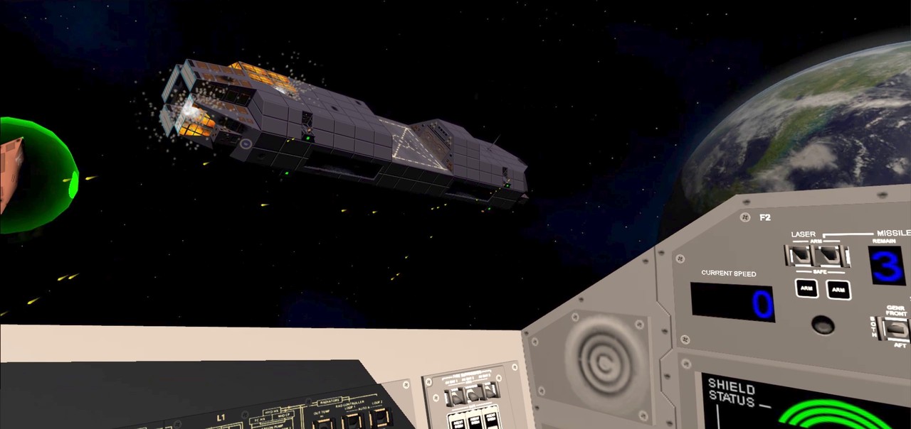
Mission 3 work
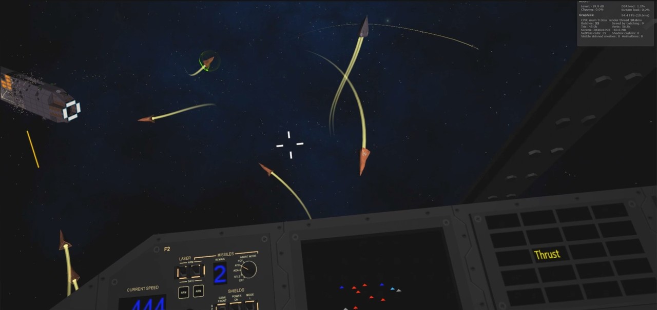
We had a meet up of many of my old work colleagues at the end of October, and I decided to demo my game at the meet. Since my Cruiser was pretty far along, I wanted to have the Mission Three (where the player is escorting the Princess's cruiser in a pirate-infested system) running at least partially. Since I had not yet done any damage handling for the cruiser, the mission could not be lost, but I thought a mission you can only win would work fine for a demo.
I spent a day or two working on the mission code, and was able to make it running pretty well by the time I wanted to demo it. It actually became quite a fun mission, so much so, that it began to affect my progress! In the highest level there are 20 pirate ships attacking the cruiser, which is escorted by six Cobras (one of them piloted by the player). I was a bit worried whether that many ships, together with all the PDC bullets flying, would run smoothly on my Samsung S6. Everything seemed to work quite fine without any noticeable frame drops. I spent a lot of time just playing the mission, while I should have worked on the game code or textures instead!
New logo
I got some useful feedback from people who tested my game at the meet. Sadly, I did not have time to show it to all that many people. Anyways, after the meet I decided to look into creating an icon or logo for LineWars VR. The Oculus store gives a lot of guidelines as to the dimensions and other attributes of the logo. As I wanted to use this logo also as an icon, I wanted it to not have tiny details, which would get lost when the image is shrunk to a thumbnail size. So, I decided to test a logo that would have just a planet and a star base, as those are perhaps the best-looking objects in my game. I am reasonably happy with the result, but I may still revisit this when I get my game further done.
Cruiser import work
Okay, next it was time to tackle the big task, adding damage states to my Cruiser object. The damage states for my fighter ships were code-wise rather easy, as I had made sure during the mesh import that every polygon (triangle) has its own vertices. This way switching a damage state for every polygon meant just switching the UV coordinates of the three vertices of this polygon. As all the polygons had their own vertices, no other polygon is affected by this UV coordinate change. The downside of this system is, that there are many more vertices in the object than would be needed just for the mesh itself. For example, my Cobra object has 66 triangles and 35 vertices originally (in Cinema 4D), but in Unity it has the same 66 triangles but 174 vertices! The reason it does not have 66*3 = 198 vertices, is that the navigation lights use shared vertices for their triangles. The navigation lights only get turned off if they happen to get hit, so they don't need the full set of damage states.
With the Cruiser, most of the body panels are rectangular instead of triangles, and they need to take damage also as a rectangular panel (consisting of two triangles). So simply giving each triangle their own vertices would not solve the damage states UV coordinate switching correctly. With the Space Station I had coded a runtime test to determine the fourth vertex of a rectangular panel (given a triangle that got hit), and I had made sure in Cinema 4D that the UV coordinates were not continuous over adjacent body panels. This was a lot of work both when modeling the object and during the game, so I wanted to do something smarter with my Cruiser object.
I decided to create an array of vertices for each triangle giving the vertices that need their UV coordinates changed whenever this triangle gets hit. These arrays would most often contain 4 vertices, but sometimes the array would have 3 and sometimes 5 or more vertices. I wanted to create this array during the mesh import, so that I could move all this code out of the actual game code. In the game code I can then just load this data from a resource file to the array of arrays in memory.
I couldn't get the Unity JSON implementation to correctly read my array of arrays, so I decided to code my own serialization and deserialization routines, using a binary resource file. This turned out to be easier than I had feared. I first experimented with the fighter ships, where I could simply use byte arrays, since they had less than 256 triangles and vertices. With the cruiser I needed to go to UInt16 values, which at first seemed to be a problem, until I found a Buffer.BlockCopy() routine. It works like memcpy(), so it can copy data from an Int16 array to byte array, like this:
    List<byte> output = new List<byte>();
    UInt16 count = (UInt16)data.tri2UV.Length;
    output.Add((byte)(count & 255));
    output.Add((byte)(count >> 8));
    for (int i = 0; i < count; i++)
    {
        int vcnt = data.tri2UV[i].Count;
        output.Add((byte)vcnt);
        byte[] temp = new byte[vcnt * sizeof(UInt16)];
        Buffer.BlockCopy(data.tri2UV[i].Select(a => (UInt16)a).ToArray(), 0, temp, 0, temp.Length);
        output.AddRange(temp);
    }
    File.WriteAllBytes("C:\\Projects\\LineWarsVR\\Assets\\Resources\\CruiserDamageData.bytes", output.ToArray());
Now that I could store the triangle-to-UV array, I needed to build it for all the 1196 triangles of the cruiser. Easier said than done... I needed to determine for every single triangle whether it is a part of a quad panel, whether it is a separate triangle, or whether it is a part of some group of triangles that need to be damaged as a group. It took me a couple of days to code the mesh import routine to handle all the cases I needed, but in the end, I managed to get all the vertices assigned to correct triangles. My cruiser mesh ended up having 1825 vertices for those 1196 triangles. This is without the eight PDC guns, which will be added to the mesh dynamically in the game. The worst-case vertex number would have been 3*1196 = 3588, so using code to group the damage panels decreased the vertex count to almost exactly half the worst-case number.
Oculus Start Program
During the last weekend of October I had stumbled across some information about a developer program called Oculus Start while reading some Oculus blog posts. I had not been aware of this program before that, and reading about it made me realize that I might actually qualify for it! The program is aimed for people working on their first VR software, but to be accepted you need to have at least an alpha build of your software uploaded to the Oculus Dashboard. Luckily, I had already uploaded a very preliminary Alpha build of LineWars VR for my tester to test it, so I had done everything that program required. I applied to the program, and got accepted within a few days, on the first of November!
The program has several benefits, the first of which I was able to use immediately. I got a free subscription for Unity Plus for one year, and Oculus emailed me an activation key for that immediately. This alone is worth several hundred dollars, but in addition to that, I am going to receive an Oculus Go device, to be able to test my game on that in addition to my Gear VR device. I also got some store credits (to be able to purchase a few games for free from the Oculus Store), access to Oculus developers, and so on. Very useful program, thanks Oculus for accepting me!
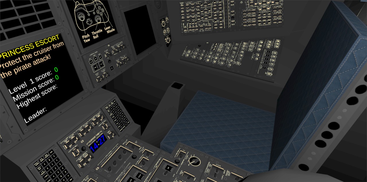
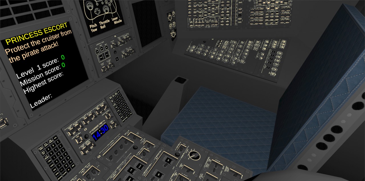
TextMeshPro for score displays
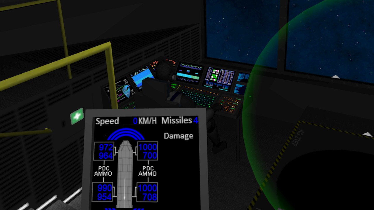
I had been thinking about how to handle the score display on one of the MFD panels. In LineWars II I had one cockpit display panel showing the short description of the mission, together with the mission scores. I could use the same UV-coordinate-based system I had used for my other cockpit displays, which is quite performant, but very inflexible. The mission description would need to be of different lengths for the different missions, and I did not want to handle that using UV coordinates and textures.
I happened to come across some information on the net that mentioned TextMeshPro using a character array as input (instead of a string), which makes it cause less garbage for the garbage collector. I decided to look into this TextMeshPro. I was not able to make my Visual Studio intellisense see the TextMeshPro, though. After a lot of hunting for an answer to this problem I found a forum post saying that a newer Visual Studio is required for some new Unity packages to work properly, and finally after updating Visual Studio I was able to use TextMeshPro properly.
TextMeshPro seemed to work fine, except that I wanted to have different colors for different sections in the text. I did not immediately find a way to do that, but since TextMeshPro came with shader sources, I decided to see if I can hack the shader code to use different colors within the same string. While I was at it, I decided to also optimize the shader for my use case.
The fragment shader of TextMeshPro has almost no code, so that is already as efficient as it can be, but I found a lot of unneeded code in the vertex shader. The original vertex shader performance was like this:
  15 work registers used, 9 uniform registers used, spilling not used.

                          A       L/S     T       Bound
  Instructions Emitted:   56      45      0       A
  Shortest Path Cycles:   28.5    43      0       L/S
  Longest Path Cycles:    33.5    45      0       L/S
I added a bit of a hacky code to change the used color depending on the vertex coordinates (as that was good enough
for my needs) and removed the unnecessary code, and got it to run like this:
  6 work registers used, 9 uniform registers used, spilling not used.

                          A       L/S     T       Bound
  Instructions Emitted:   34      20      0       A
  Shortest Path Cycles:   17      20      0       L/S
  Longest Path Cycles:    17      20      0       L/S
A good reduction on both the arithmetic and load/store operations. I might still figure out some other way
to show the scores, but I am using TextMeshPro for now, at least.
OVR Metrics Tool
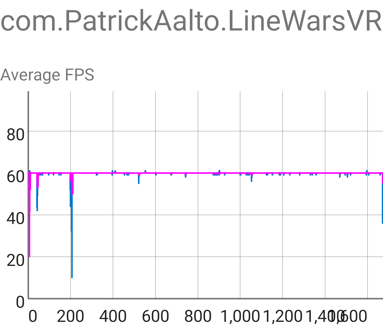
This month I also (finally) installed OVR Metrics Tool on my Samsung S6, to be able to see and log the actual performance of my game. Oculus requires all VR software for Gear VR to run at constant 60 fps, or they won't be accepted to the store. If the framerate does not stay at constant 60 fps, players will see judder and stutter and will easily get nauseous. The only exceptions to this rule are when the screen is black and/or the game is just starting.
I tested my game by first going to the main menu (obviously), and then going to the demo game. I let it run a little while, and it looked like it stayed at nearly constant 60 fps. I then switched to the Mission 3, which has a lot of ships fighting each other in the later levels. I ran through the whole mission, all ten levels (which was pretty easy now that you cannot die yet in that mission), and was happy to see only a couple of larger frame drops. I will need to find out what causes these very occasional frame drops (unless they are caused by some background process running on my phone), but other than those, the game ran at very neat 60 fps even on my Samsung S6 (which is the slowest supported phone in Gear VR) using 1.4 times the recommended screen resolution. There should be no problems running the game on faster devices, and there seems to still be some headroom for additional features or eye candy.
The three large drops in the image below are first the start of the game, then switching to the Demo Game, and then switching back to Menu and immediately to Mission Three. The screen fades to black during these times, so those frame drops are not noticeable in the game. I also still perform a lot of initialization at the start of each mission which I could move to the start of the whole game. This should shorten the length of those mission switch frame drops.
Dithering algorithm performance tests
While I was surfing the Oculus blog posts, I also ran into some information about efficient dithering algorithms in a post called Tech Note: Shader Snippets for Efficient 2D Dithering. Ever since I switched to using proper dynamic ceiling-light-based lighting for my Cobra cockpit, I had been suffering from color banding especially on the foot well side panels. The lighting changes so gradually over the large panel, that the 256 gray shades of the standard 16.7 million color palette are not enough to display all the shades. Here below is an (exaggerated by using a Gamma value of 2.0) image of the original cockpit shader result, where you can clearly see the color banding on the foot well side.
I had also recently watched a Games Development Conference video Low Complexity, High Fidelity: The Rendering of INSIDE where the programmers basically state that not using dithering in a shader is pretty much inexcusable, so I decided to finally do something about that color banding issue. I wanted to make sure I use as efficient dithering algorithm as possible, so I did not believe immediately what the Oculus tech note states, instead I did some empirical testing myself. I looked for some shader dithering implementations from Shadertoy, and immediately found a shader called dithering: Color Banding Removal, which contained several different dithering algorithm implementations. I implemented all those (along with the Oculus tech note one) into my Cobra cockpit shader (I found a helpful article about the syntax differences called Unity Shadertoys (a.k.a Converting GLSL shaders to Cg/HLSL)), and then tested each one of them. I ran the Mali Offline Compiler for each dithering version, and also visually evaluated the result in my cockpit.
In this table I have collected the results of my tests.
| Algorithm | ALU cycles | Load/Store cycles | Texture cycles | Visual quality |
|---|---|---|---|---|
| 2x2 ordered dithering, ALU-based | 5.5 | 1 | 0 | Looks good |
| 2x2 alternative version | 4 | 1 | 0 | Looks good |
| 8x8 ordered dithering, texture-based | 1 | 1 | 1 | Unknown, needs proper texture |
| InterleavedGradientNoise | 3 | 1 | 0 | Looks good |
| ScreenSpaceDither | 2.5 | 1 | 0 | Looks good |
| CeeJayDK dither | 3 | 1 | 0 | Looks good |
| bluenoise from texture | 3.5 | 1 | 1 | Unknown, needs proper texture |
| triangularly distributed noise | 8 | 1 | 0 | Looks good |
| uniform noise by 1 LSB | 4 | 1 | 0 | Looks good |
| Oculus Tech Note | 2 | 1 | 0 | Looks OK |
So, it looked like the 8x8 texture-based dithering would be fastest, followed by the Oculus Tech Note algorithm. I didn't take the time to create a proper dither texture to check the visual quality of the texture-based algorithms, as I was more focused on the ALU-only solutions. It looked like the Oculus implementation is indeed the most efficient ALU-only dithering algorithm, so I ended up using that in my cockpit shader. I chose the k0 and k1 constants from the Shadertoy ScreenSpaceDither algorithm, which probably were not exactly optimal, but they seem to work fine. This is what the algorithm implementation looks like in my fragment shader:
    // Dither algorithm for the fragment shader, from https://developer.oculus.com/blog/tech-note-shader-snippets-for-efficient-2d-dithering/
    float4 oculusdither(float2 pos)
    {
        float t = frac(pos.x * 171.0 / 71.0 + pos.y * 231.0 / 71.0) / 255.0;
        return float4(t,t,t,0);
    }

    ....

    // i.lightData.x contains the ceiling light multiplier for the vertex
    fixed4 shCol = tmp > 0.5 ? col : col * i.lightData.x + oculusdither(i.vertex.xy);
Here below is an image of the cockpit, using this dithering algorithm. This has also exaggerated Gamma value of 2.0
to bring out the gray shades. The color banding is not completely gone (due to the simplicity of the algorithm and
sub-optimal k0 and k1 constants), but it is far less distracting.
Cruiser damage states work
As I had created code in the Cruiser mesh import to precalculate the vertices that need their UV coordinates changed when a triangle gets hit, it was now time to create the damage textures. Texturing is something that I do not enjoy doing, so this work feels really boring and progresses quite slowly. I keep getting distracted by things like the dithering algorithms and OVR Metrics Tool testing, when I should have been working on the damage textures. I have now been working on the damage state textures for two weeks, and they are still not completely done. I think I am over half way done, though, so perhaps the end of this boring work is beginning to be in sight.
One of the biggest hurdles with these damage states were the main armor panels of the Cruiser. I had used a system in the Space Station where each quad (two triangles) are split into four armor panels. I had coded the damage states to be armor-panel-specific, which meant that I needed to have the textures contain all combinations of four adjacent armor panel damage states for each quad. The space station only had three damage states, so this was not overly difficult. However, with the cruiser I wanted to have four damage states (plus "internal fire" animation as the fifth state), so I would need 4*4*4*4 = 256 different damage state images for each polygon quad. However, I could reduce the amount of needed textures by using symmetry, so that for example a quad that has a hole in one corner could use the same texture slot regardless of which corner the hole is in. This works as long as I keep the textures symmetrical (so that going to the next damage state of one corner still keeps the other corners looking the same, even if I need to reorient the texture slot) and I remember to also adjust the tangent vector direction when needed.
The problem was figuring out the best way to use my limited texture atlas space for all these different damage state slots. I thought there must be an algorithm to figure out the best fit for this, but I couldn't even figure out any search terms to use to be able to search for one! In the end I just had to bite the bullet and manually try to find how to fit the damage states to the texture atlas. I had two sizes of armor panels in the ship, so I also used two different sets of damage states (in hindsight I think I perhaps could have used only one, even thought that would mean stretching the panels). The larger panels are 128x80 texels per quad, and the smaller panels are 128x66 texels per quad. This meant that each armor panel is either 64x40 or 64x33 texels. I allocated two grids of 16 by 4 armor panels (or 1024x160 and 1024x132 texels), and then kept reordering them until I was happy with the result. I was not able to find room for every single combination, but most of the early states are included. I figured if many of the adjacent armor panels are already damaged, it does not matter if a new hit causes a bit more damage than normal. Perhaps the underlying ship structure had already weakened, or something...
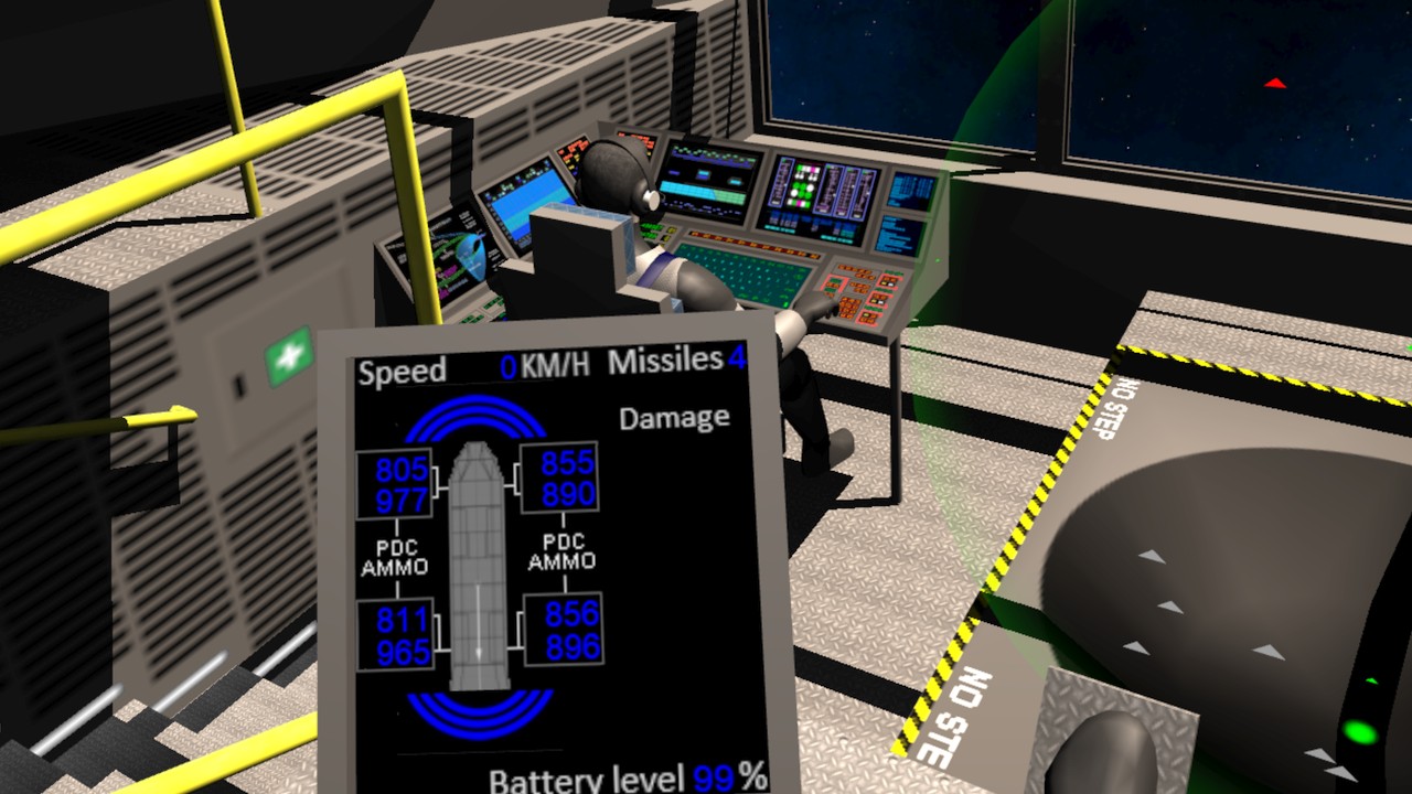
I then also added a system like the triangle-to-UV array for an array that determines how the "internal fire" animation is handled. It looked weird if the fire goes from the rear of the ship towards the front when the ship is moving (even though in zero gravity this would be quite fine), so I made sure the fire always goes from front to back. The new triangle-to-fire list allowed me to handle this without much trouble. As it is difficult to describe how the system works without images and videos, I decided to record a short video with the cruiser damage states in action. Here is first a single screen capture frame of the video, showing some damaged panels and some internal fire, and then the actual video is below this screen capture. The video is from Mission Three, where up to 20 pirate ships are attacking the Princess's Cruiser.
That is all for this blog post! Thanks for reading!
Oct 19th, 2018 - Cruiser Bridge Work
I was a bit sick during the end of September, so I got somewhat behind schedule with my project. It does look like my internal goal of getting the game done by the end of this year would not have happened even if I had not gotten sick, as I still have so much work to do. So, the new goal is to get the game released before the next summer. Anyways, during the past month I have mostly been working on the Cruiser Bridge object, because in several missions you can pilot a battlecruiser in addition to the fighter ships.
Teleport Between Different Types of Ships
The first step in making it possible to pilot a battlecruiser was to enable teleporting between different types of ships. Same as in LineWars II, in LineWars VR you can teleport between all the friendly ships, and you also get automatically teleported ("Emergency teleport!") to another ship when the ship you are currently piloting gets destroyed. Teleporting to a different type of ship (for example from a Cobra fighter to the battlecruiser) needs all the cockpit mesh objects and instruments to get switched over, and also the camera position needs to switch to the correct position in the cockpit of the new ship.
I solved this problem by having all the needed cockpits and their instrument objects in the scene, with the not currently active cockpit disabled. I changed my instrument handling code to have an array of InstData classes, each of which contains the necessary data (including pointers to the scene objects, the camera positions, UV coordinate indices and so on) for a certain cockpit type. When the user then teleports between different ship types, I switch the index into that InstData array, while activating the scene objects of the new InstData item and deactivating them for the old InstData item. This way I am always handling only the instruments of the currently active cockpit type.
Additional Shadows to Cruiser Bridge
After generating a neat procedural shadow system for the Cruiser object (as described in the previous blog post), I began experimenting with some additional vertex-specific shadows to the Cruiser Bridge model as well. Back in April I had created a shadow system where all the windows and window struts are handled, so that only the areas where the sun is shining through the windows are lit. However, this still left all the other parts of the bridge that should cause shadows unhandled. For example, it looked pretty fake when the support leg of the weapons officer instrument console caused no shadows on the floor, even though the floor had shadows from the window struts.
The original fragment shader from April had performance like this:
  4 work registers used, 1 uniform registers used, spilling not used.

                          A       L/S     T       Bound
  Instructions Emitted:   52      6       1       A
  Shortest Path Cycles:   1       1       1       A, L/S, T
  Longest Path Cycles:    8.5     6       1       A
I began optimizing the fragment shader, using the tricks I learned when coding the Cruiser fragment
shader, like using abs() function when possible with the shadow checks. I also moved the
dot(v.vertex.xyz, _ShadowsLightDir) calculation from the fragment shader to the vertex shader,
as that changes linearly within the polygon. I then added the additional two-plane shadow checks
using code from the Cruiser object, like this:
    if ((abs(i.shadowPos.x) <= i.shadowData.x && abs(i.shadowPos.y) <= i.shadowData.y) ||
        (abs(i.shadowPos.z) <= i.shadowData.z && abs(i.shadowPos.w) <= i.shadowData.w))
        return shCol;
I was very happy to notice that I was able to keep the performance of the new code exactly the same
as the original code, even though the code is now able to handle two extra shadow planes
in addition to the window shadows for each fragment!
  4 work registers used, 1 uniform registers used, spilling not used.

                          A       L/S     T       Bound
  Instructions Emitted:   44      6       1       A
  Shortest Path Cycles:   1.5     2       1       L/S
  Longest Path Cycles:    8.5     6       1       A
Okay, so the fragment shader change was a simple one, but the vertex shader needed a lot more work, as I needed to add the shadow texture lookups and the shadow plane calculations. I decided to test a system where the vertex shader itself calculates the sun direction "quadrant", instead of having separate sets of color and UV2 arrays like I had in the Cruiser object. I thought I could get by using much fewer shadow planes here, so I split the 256-column texture into four 64-column blocks, depending on whether the sun is behind, in front, left, or right of the ship. I did not think I needed to worry about the up/down direction, as the windows are mostly on the upper half of the cruiser bridge, so if the sun is below the ship, there are not a lot of objects causing extra shadows anyways.
As the texture only has 256 different values per pixel, I needed to figure out how to map these values to the cruiser bridge coordinates. The bridge is 12 meters wide, 3.75 meters high, and 7 meters deep (or actually even deeper, but I am only interested in the area that the pilot is normally seeing). After looking at the structure of the bridge, I noticed that the highest items that would cause shadows are only 245 cm above the floor, so I could neatly fit the Y coordinate into 256 items if I used 1 cm granularity. Also, any objects in the Z direction causing shadows are between 0.6 and 5.7 meters along the Z axis, so that 5.1 meters range would fit into 256 if I used 2 cm granularity for the Z coordinate. This still left X coordinate, with the difficult 12 meters range.
I decided to split the X coordinate into negative and positive halves, as the bridge is very symmetrical. I also decided not to have any shadow-causing objects on the far edges, so I could use the same 5.1 meters range with 2 cm granularity for the X coordinate. This just meant that I had to use some extra code in the vertex shader to determine whether the X coordinate should be negative or positive. For the other axis I could simply choose a suitable zero position, for the Y coordinate this is naturally the floor (at -2.25 meters in my object), and for the Z coordinate it was the 0.6 meters Z position.
In my Cruiser vertex shader, I had used three separate plane configurations, with the planes always aligned by the coordinate axis. However, as I already had angled shadow planes for the side windows of both my Cruiser Bridge object and my Cobra cockpit, I thought I could try to use that full plane equation instead of forcing the shadow planes to be axis-aligned. The problem with this was that the plane equation has a constant d term, which should have the full float accuracy, so I could not have that value in the texture. At first, I thought about adding another UV coordinate set to handle this value, until I realized what I could actually calculate the d term in the shader!
The d term of the plane equation is actually the negative value of the dot product of any point in the plane and the plane surface normal. I could use the center point of the plane (which I would need in the shader anyways, to be able to use the abs() method of checking the plane extents) as the "any point", and the surface normal should be a unit vector, so it could be put into the texture, same as any standard Normal Texture that Unity uses.
Next, I spent some time simplifying the equation for the vertex projection onto the shadow plane that I would need in the vertex shader. These are the terms I use in the following equations:
V = vertex (point), N = plane normal vector (unit length), C = plane center (point), L = light vector (unit length)As described in the algebraic method for the Ray-Plane intersection, the starting point for projecting the vertex onto the shadow plane (in other words, determining the intersection point of the plane and the ray starting at the vertex and following the light vector) is this full equation (where the constant term d is replaced by the full -dot(C,N)):
V + (-(dot(V,N) + -dot(C,N))/dot(L,N)) * LFor my purposes, I still needed to subtract the plane center point from that result (to center the interpolators around the plane in order to use abs() less-than checks for the plane boundaries), so the actual equation I used was the following:
interpolators = V + (-(dot(V,N) + -dot(C,N))/dot(L,N)) * L - CWriting it out for the X coordinate (as an example) produced the following equation:
X interpolator = Vx - (Vx*Nx+Vy*Ny+Vz*Nz-(Cx*Nx+Cy*Ny+Cz*Nz)) / (Lx*Nx+Ly*Ny+Lz*Nz) * Lx - CxLooking at that equation I noticed there were a few duplicated terms, and thus I was able to simplify the equation by subtracting the center point from the vertex separately:
X interpolator = (Vx-Cx) - ((Vx-Cx)*Nx+(Vy-Cy)*Ny+(Vz-Cz)*Nz) / (Lx*Nx+Ly*Ny+Lz*Nz) * LxThis reduced the number of dot products from three to two, also getting rid of the constant d term in the process. Here below is the actual vertex shader code, where you can see these equations being used. The first line of the code calculates the (horizontal) index into the texture, based on the quadrant of the light vector and the input green channel of the mesh color. I set up these mesh colors in my MeshPostProcessor code that gets run when the mesh gets imported into Unity. I also generate the texture image in this code. The first row of the texture contains the plane boundary extents, the second row contains the first plane normal and center X-coordinate, the third row similarly the second plane normal and center X-coordinate, with the last row containing the Y and Z-coordinates of the plane centers.
    // Calculate polygon-specific shadows
    fixed idx = v.color.g + sign(_ShadowsLightDir.x)/8.0 + 0.125 + sign(_ShadowsLightDir.z)/4.0 + 0.25; // Texture index + light dir quadrant of the texture to use
    // Shadow extents are in the order xzxy (sort of like using Y-plane and Z-plane)
    o.shadowData = tex2Dlod(_ShadowTex, float4(idx, 0.1, 0, 0)) * float4(5.1, 5.1, 5.1, 2.55);	// Y has 1 cm granularity, other axis 2 cm
    half4 n1 = tex2Dlod(_ShadowTex, float4(idx, 0.3, 0, 0)) * half4(2,2,2,5.1) - half4(1,1,1,0); // Plane 1 normal + X center
    half4 n2 = tex2Dlod(_ShadowTex, float4(idx, 0.6, 0, 0)) * half4(2,2,2,5.1) - half4(1,1,1,0); // Plane 2 normal + X center
    half4 c = tex2Dlod(_ShadowTex, float4(idx, 0.8, 0, 0)) * half4(2.55, 5.1, 2.55, 5.1) + half4(-2.25,0.6,-2.25,0.6); // Plane 1 yz and Plane 2 yz
    // We are only interested in the vertex position relative to the shadow plane center
    half2 t = v.vertex.x >= 0.0 ? half2(n1.w, n2.w) : half2(-n1.w,-n2.w);  // Plane X-center signs follow the vertex X-coordinate signs
    half3 a = v.vertex.xyz - half3(t.x, c.x, c.y);
    half3 b = v.vertex.xyz - half3(t.y, c.z, c.w);
    // Project the vertex onto the shadow planes
    a = a - dot(a, n1.xyz) / dot(_ShadowsLightDir, n1.xyz) * _ShadowsLightDir;
    b = b - dot(b, n2.xyz) / dot(_ShadowsLightDir, n2.xyz) * _ShadowsLightDir;
    o.shadowPos = half4(a.x, a.z, b.x, b.y);
The vertex shader performance before adding all these lines of code was like this:
  8 work registers used, 8 uniform registers used, spilling not used.

                          A       L/S     T       Bound
  Instructions Emitted:   32      23      0       A
  Shortest Path Cycles:   17.5    23      0       L/S
  Longest Path Cycles:    17.5    23      0       L/S
After adding the new code, the performance changed to this:
  7 work registers used, 7 uniform registers used, spilling not used.

                          A       L/S     T       Bound
  Instructions Emitted:   53      21      4       A
  Shortest Path Cycles:   28      21      4       A
  Longest Path Cycles:    28      21      4       A
I was actually able to save on the load/store operations (which are the more critical GPU cycles, as they
are subject to possible stalls due to cache misses). The arithmetic operations increased quite a bit, though,
so it is now even more important to try and keep the vertex count of my Cruiser Bridge as low as possible.
Weapons Officer Avatar Work
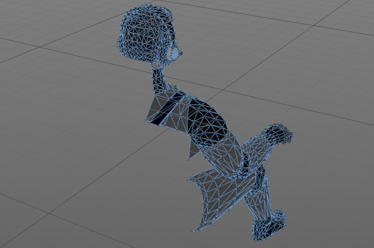
The Cruiser Bridge would be rather empty if it did not have any other people besides the player. Thus, I always wanted to populate the bridge with a couple of human characters, at least the weapons officer and navigator, sitting below and in front of the captain of the cruiser. The problem with these extra human characters was, that I would need to model their heads! Modeling the human head (convincingly) is notoriously difficult. Luckily my characters were facing away from the player, so at least I did not need to worry about their faces!
Even with their faces hidden, I would still need to model some hair and their ears, which felt both rather difficult and expensive considering the polygon count that would be needed for convincing results. I thought about having them wearing a helmet, but that felt somewhat silly. Nobody on Star Trek or Star Wars wears a helmet when on the bridge of a capital ship, so they should not do that in LineWars VR either! I then figured out that they would need to be wearing some communications devices in their ears anyways, so why not wear full blown headphones? I could then hide their ears and part of their hair easily underneath the headphones (which would be considerably simpler to model, just some donuts and cylinders joined together)!
So, I went to work, copying the pilot avatar legs and arms, and then going back to my old animation project character for the head and hair. I reduced the head polygon count considerably, and then began modeling the headphones. The head with the hair ended up using 300 vertices, and the headphones 257 vertices. The headphones have a microphone, which is probably using a bit too many vertices, as it is only a few pixels in size in the game, so I will perhaps still adjust that object a bit. The rest of the character uses 506 vertices, so the total number of vertices is a bit over a thousand. All in all, I think I managed to create a pretty neat looking virtual person sitting on the weapons officer console. Much of the character is hidden behind the seat, so I only bothered to model the parts that will be visible.
Cruiser Bridge Consoles
Until now my weapons officer and navigator consoles had been without proper textures. I grew tired of watching them, and decided to finally create some textures on them. I reserved a 190x600 area of the common cockpit texture for these consoles, and began looking for some reference images. I made some Google image searches with "star ship bridge consoles" and similar search terms, and found a lot of images, mostly for the Star Trek bridges. These were not exactly what I wanted, but I found some display panel images that looked pretty good, so I used those as a starting point, and then began working on my texture.
I wanted to have the consoles consist of two parts, an upper display section and a lower keyboard section. For the display part I ended up with two large displays and two small displays, plus a warning light panel in front of the console operator, and just two large panels and the warning lights on the side console. I also decided to reuse the left/right display images, so that the left-hand side console shows the same image as the right-hand forward console, and wise versa. This saved on the texture memory usage and allowed me to have larger display images. For the keyboard part I just used some real keyboard images, shrunk them to a suitable size, and then added some side key panels, with red keys for the weapons officer and blue keys for the navigator.
I had also noticed when watching some Star Citizen videos, that they seem to have some text scrolling on their various secondary displays in the larger ships. I thought that was a neat idea, and made one of the smaller displays on either side perform similarly. For the text that scrolls, I found out that I could let Irfanview load my LineWars VR project notes, so that it converted it to an image, and then I could just crop a suitable part of that image for my scrolling text! Since I already have to update the UV coordinates of various indicators on the pilot display panels (like the PDC ammo counters), I added these scrolling displays to my instrument object and added simple code to scroll the UV coordinates every now and then. The result looked pretty nice!
Here below is what the weapons officer console looks like with the sun shining on it. This image also shows the weapons officer avatar and various extra shadow planes, for example for the yellow side railings and the console leg. There are still many areas that should have additional shadows, but many of those would require more than two shadow planes, or are otherwise difficult to set up, so I am thinking I would rather leave those out than to have shadows that look weird.
The bridge walls are still pretty much work-in-progress as far as the textures are considered. Here I am experimenting with a sort of metal mesh grid texture for the walls (assuming even in the future keeping the space ship as light as possible is advantageous). Below is what the console looks like when the sun is not shining on it, with the displays and buttons glowing in the dark.
Compute Shader Experiment
After testing the PDC bullet movement code on the actual Gear VR device, it looked like there were some infrequent frame skips whenever there were a lot of bullets flying. So, I decided to revisit the bullet movement code. My original code used up to 400 separate GameObjects, all using the LineRenderer to draw a simple line. I used local coordinates for the line ends, letting Unity then dynamically batch all the separate GameObjects into a single big mesh for rendering. I thought that perhaps it would be smarter to have just a single GameObject, which could even be located at the world origin, and then just use world coordinates for the line ends.
After making that change, I then began to wonder whether a compute shader would be usable when targeting Android devices. It looked like my Samsung Galaxy S6 does support compute shaders, even though the Unity editor (when targeting Android) does not. I found a good YouTube tutorial for Unity Compute Shaders, and decided to experiment with the ideas shown in that tutorial.
After a lot of trial and error (and some bug hunting, and fighting with an issue where the actual display shader does compile, but only produces purple result) it seemed like my Samsung Galaxy S6 does not support StructuredBuffers in the vertex shader (as per this Unity forum thread). That was pretty annoying. My fallback option was to move the vertices (and handle the collision tests) in the compute shader, then use GetData to transfer the vertices from GPU to CPU, and then use mesh.vertices to send them back from CPU to GPU. This is far from optimal, but seemed to finally allow my compute shader to work.
I then checked the resulting StopWatch Ticks when running the game on my Gear VR (as I had noticed that the System.Diagnostics.Stopwatch gives sensible-looking values also on Android, not only when running in the Editor). Originally the code that moved and tested the bullets for collisions (for the target and viewer ship) took around 2750 ticks to run. My new compute shader actually checked collisions with the 8 closest ships, ordered in priority so that close enemy ships will always get included, and neutral objects like asteroids get left out of the collision tests if there are already eight more important close objects. It took only around 500 ticks to prepare the data for the compute shader per frame, but calling the GetData routine to get the new vertex positions and the hit test results from the compute shader to the CPU code took a mind-boggling 110000 ticks! I had read that the GetData call needs to do some synchronization between the GPU and CPU and thus may take a while, but I did not think it would take two orders of magnitude longer than just moving the bullets on CPU! In addition to this, setting the vertices of the mesh took another 200 ticks.
So, it seemed like my experiments with the compute shader were mostly wasted time. I decided to use the shader code rewritten in C# on the CPU for my bullet movement and collision tests. It takes between 2000 and 6000 ticks when moving 512 bullets that never hit the targets, but in real situation and with only 384 bullets the code mostly takes around 1100 ticks, which I thought was pretty acceptable. I just need to optimize some of my other code if I begin to experience frame drops. I have also considered porting some of my code to a native plugin, but haven't yet had a pressing need for that. I may look into that if I need to make some major code speedups.
AI Ship Movement Improvements
My old LineWars II game had a demo game, where you could just watch the game play against itself, in the form of watching a group of Cobra fighters attacking an enemy StarBase, protected by Pirate ships launching from the StarBase. I wanted to have a similar demo game in LineWars VR, although being virtually in a ship that moves and bounces around is a pretty sure recipe for nausea. However, you can easily take control of the ship by pressing the Teleport key, so I thought this could work also in the VR environment. The problem was, that my ships steered around so jerkily, that even I got nauseous within just a few seconds of watching the demo game! Something needed to be done about that.
I spent some time looking into various filtering algorithms, but did not find a suitable one for my needs. I thought the ideas in a standard PID Controller were applicable, but my problem was that the set point varies, as the ship is targeting a moving object. After a lot of tinkering with the code, I did finally manage to create a system that sort of follows the PID controller principle, with me using only the proportional and derivative terms of the control loop. My ships all have a maximum turning rate that they cannot go over, but I used the PID controller when determing how much to change the current turning rate. This made the ships rotate much smoother, so that I did not immediately get nausea when watching the demo game.
Spacescape for Skyboxes with Nebula Backgrounds
I had already a while ago run into a program called Spacescape by Alex Peterson, when I was looking for some skybox ideas. This is a neat free tool for creating space skyboxes with stars and nebulas. I just hadn't had time to look into this program further. Here below is a picture of one of the sample scenes in the program.
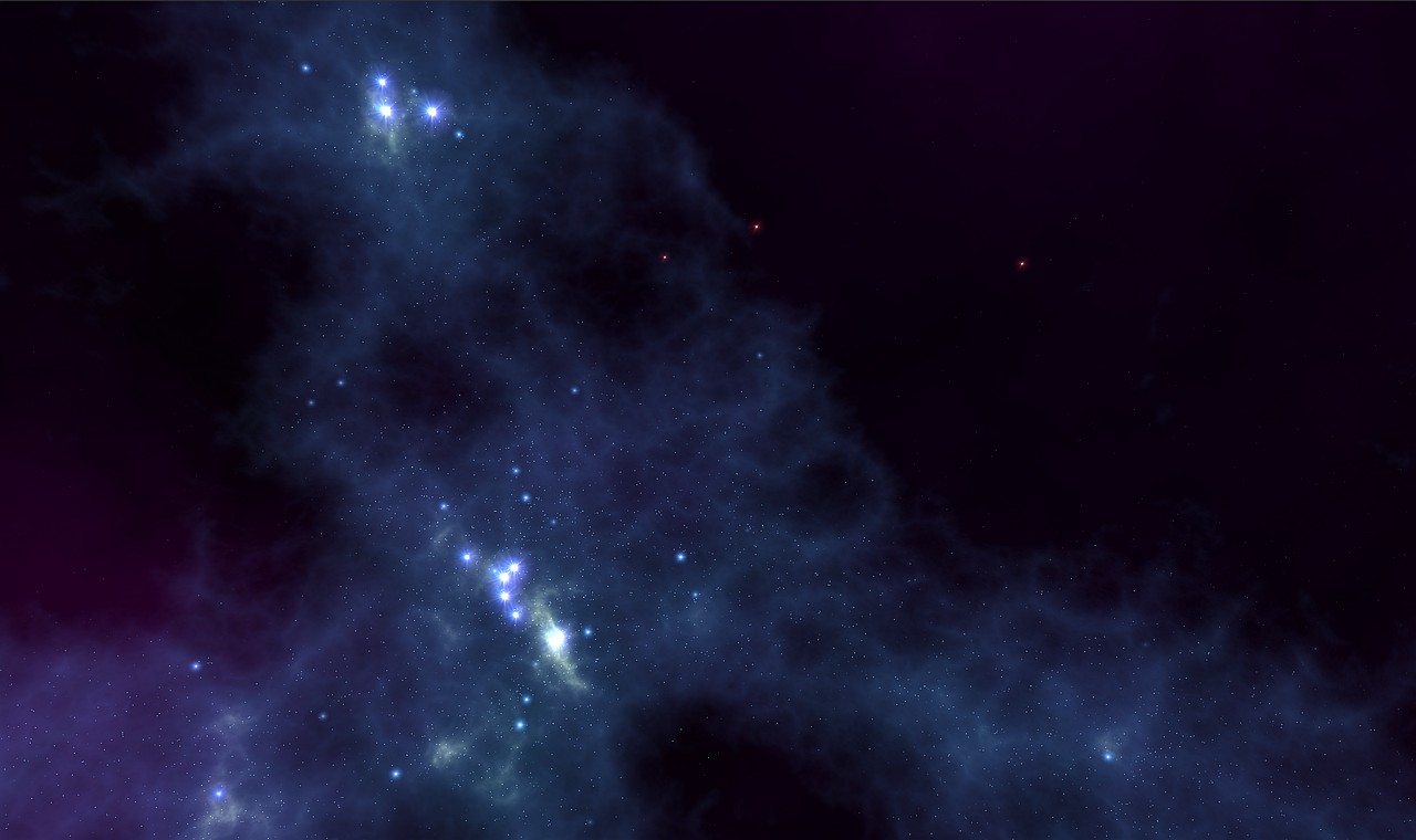
I wanted to finally look into this program a bit more thoroughly, mainly to see how I could use it together with the environments (the planet, moons and a sun) I had created in Cinema 4D. I took one of the sample files (called "Green Nebula"), and played around with it a bit (changed the green color to blue, and changed some star colors as well), and it began to look quite usable for my game. I figured there would probably be two ways to combine Spacescape with Cinema 4D, I could either render my planets and such from Cinema 4D separately and use them as billboard textures in Spacescape, or I could use the Spacescape images as background images in Cinema 4D.
I decided to first experiment with the latter option, as I am still much more familiar with Cinema 4D than with Spacescape. I replaced my background stars in my C4D skybox scene with a Background object, and attached the correct image from the Spacescape export images as the Background texture. I then rendered out the image from Cinema 4D, and compared the result with the Spacescape image. The images were correctly sized and oriented, but the stars in the Cinema 4D output were dimmer. I tried to figure out what caused this. I suspected too heavy antialiasing, and switched that from Best to Geometry, but that did not help. I then added some sharpening, but that did not help either. Finally, I figured out that the smoothing was caused by the texture sampling in Cinema 4D, which by default uses MIP sampling. I switched that to None, so that the background texture gets handled pretty much as-is, and finally got an image where the background stars and nebula were practically identical to the original image from Spacescape, with the planet added to the foreground. Now I just need to get more familiar with Spacescape to be able to add a nice variety of space background skyboxes to my game.
Next Steps
Next, I believe I will need to work on the cruiser damage textures and the collision detection. I would also need to create the female navigator avatar, and create some objects and textures on the rear of the cruiser bridge, and after those I should be able to make the third mission playable. The second mission is actually only waiting for the scoring system, as I do not want to make several missions and then add the scoring system to all of them separately. After that I could have the first five missions running. The sixth mission needs the player to be able to control a pirate fighter, so the next step will be to create the pirate ship cockpit. Then I still need to create the alien mothership, to be able to finally add all the single player missions. Then I can start working on the multiplayer features, and the configuration screen. Still a lot of work to do, in other words!
Thanks again for your interest in my LineWars VR game project!
Sep 15th, 2018 - Cruiser Work
During the past month I have mainly worked on the Cruiser game object. I finished the object mesh, improved and completed the dynamic self-shadowing system, textured the model, and also worked on the PDC (point defense cannon) rotating and firing system. These battlecruisers feature on several of the missions in my game, so along with the Space Station they are the "hero" objects of the game.
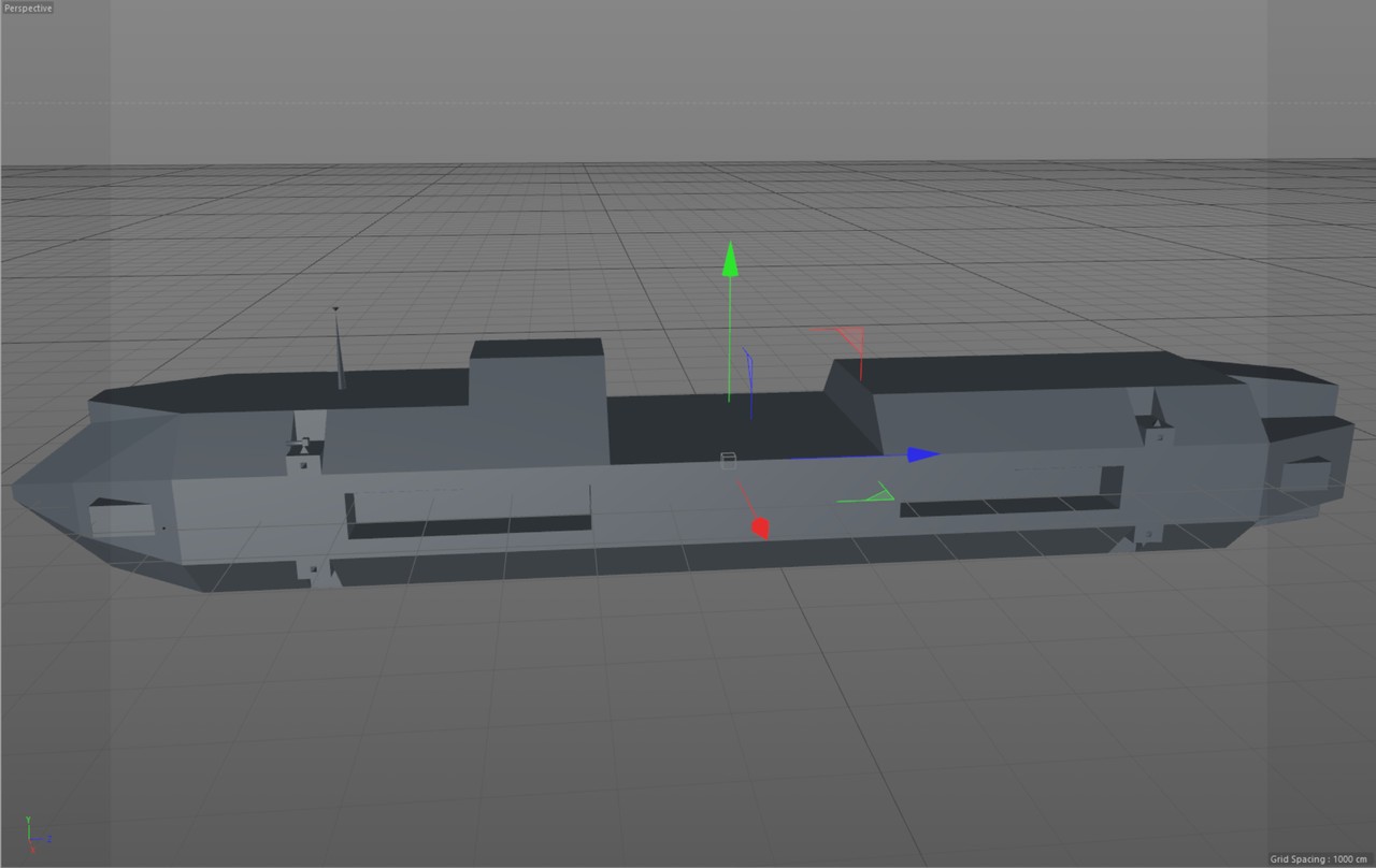
Modeling the Cruiser
I wanted to have the cruiser model relatively complex, but because in many missions there will be several cruisers in the scene, it should not be overly complex. Also, as I needed to manually configure all the shadow planes for my dynamic self-shadowing system, I did not want to have to do a huge amount of work. I ended up with a somewhat cigar-shaped design, with a shuttle landing pad in the center, a missile tower on top, some recessed living quarters on the sides, and eight PDC extrusions strategically placed to have maximum coverage. The image below shows only one of the PDC guns, as I decided to actually generate these programmatically while importing the mesh. This way I could exactly determine the normal vectors and UV coordinates, and which vertices are shared between the triangles. It was important to have as few vertices for each PDC as possible, as I plan to have all of them moving and tracking enemy targets.
Shadow System Revamped
As I described in my Apr 21st, 2018 blog post, I had already back in April worked on a self-shadowing system for my Cruiser model. I had manually configured the few shadow areas I had, mainly just to confirm my system worked. I had left many of the needed shadows still unconfigured, as the model itself was not yet finished. Now that my model was much more complex, I thought it was too much work to configure everything manually the way I had done previously. So, I decided to try to do as much of the configuration programmatically as I could.
The first step was to move the shadow configuration from the Awake() routine to my MeshPostProcessor() routine, so that it will be done while the model gets imported. At first, I created code that generates a new C# source code file containing a static array. However, as this file was over two megabytes in size, and had over 16.000 array items, it took forever to parse when the game was loading! In the editor it only took a few seconds, but in the actual Gear VR I waited a couple of minutes for the scene to start, and while it still had not started, I abandoned this idea. I am more used to working with non-managed languages, where such a large array in a source file simply gets compiled to a binary and is as fast as any binary data. Looks like in C# the system parses this source file during runtime, which obviously is not what I wanted. Since that did not work, I decided to simply write a JSON file containing the data, and loading that as a resource when the game starts. This seemed to work much better.
In my shadow data generator, I manually configure these three pieces of information for every shadow plane:
- The shadow plane location, orientation and extents (in local coordinates, obviously).
- Sun directions when this shadow plane will cause shadows. These directions are a combination of -X, +X, -Y, +Y, -Z, and +Z directions, so there are 8 possible combinations.
- A bounding volume of polygons in the Cruiser object that are affected by this shadow plane.
However, while I was adding these shadow configurations, I realized that my shadow system is still lacking some features. For example, I could only have a slope on the X-coordinate of the shadow plane, but there were several occasions where I would need to have other slopes as well. I tried to add some new code into my vertex shader, but I could not figure out a way to add more features without introducing register spilling (meaning I ran out of available GPU registers). After a while fighting with this, I decided to refactor the whole system.
At first, I looked into taking advantage of the new UV coordinate sets introduced by the later Unity versions. Nowadays you can have up to 8 sets of UV coordinates, while I only had 4 in the version of Unity I started coding LineWars VR with. However, adding even more data that I should update dynamically did not sound all that efficient. Instead of adding more data, I experimented with various ways to more efficiently use the existing UV2, UV3, UV4 and Color arrays. One idea I got was that instead of comparing the shadow plane interpolators against minimum and maximum values, I could compare just the absolute interpolator value against a single maximum value, if the plane center is at zero. This change was still not enough for all my needs, but it made the fragment shader nicely somewhat more efficient. Originally the fragment shader shadow calculation looked like the following (it could only handle the maximum limit in the Y-direction, there were no checks for the minimum value):
    fixed sh = (i.shadowPos.x <= i.shadowData.x && i.shadowPos.x >= -i.shadowData.x && i.shadowPos.y <= i.shadowData.y) ||
               (i.shadowPos.z <= i.shadowData.z && i.shadowPos.z >= -i.shadowData.z && i.shadowPos.w <= i.shadowData.w) ? i.uv.z : i.uv.w;
with a performance like this:
  3 work registers used, 1 uniform registers used, spilling not used.

                          A       L/S     T       Bound
  Instructions Emitted:   18      5       2       A
  Shortest Path Cycles:   5       4       2       A
  Longest Path Cycles:    6.5     5       2       A
It had 18 arithmetic operations, and spent 6.5 GPU cycles. The new code checks for two shadow planes
using abs(), so it can handle limits in all directions:
    fixed sh = (abs(i.shadowPos.x) <= i.shadowData.x && abs(i.shadowPos.y) <= i.shadowData.y) ||
               (abs(i.shadowPos.z) <= i.shadowData.z && abs(i.shadowPos.w) <= i.shadowData.w) ? i.uv.z : i.uv.w;
The performance of the new code looks like this:
  3 work registers used, 1 uniform registers used, spilling not used.

                          A       L/S     T       Bound
  Instructions Emitted:   14      5       2       A
  Shortest Path Cycles:   3       4       2       L/S
  Longest Path Cycles:    4.5     5       2       L/S
The number of arithmetic instructions dropped from 18 to 14, and the cycles by 2! That was a nice performance
boost combined with better features, so it was a win-win situation! The reason why using abs is so much
faster seems to be because this way the shader can calculate all four comparisons in one go, as all the
comparisons are the same (less-than-or-equal). The compiled code looks like this:
    u_xlatb2 = greaterThanEqual(vs_TEXCOORD4, abs(vs_TEXCOORD3));
    u_xlatb2.x = u_xlatb2.y && u_xlatb2.x;
    u_xlatb2.y = u_xlatb2.w && u_xlatb2.z;
    u_xlatb21 = u_xlatb2.y || u_xlatb2.x;
    u_xlat21 = (u_xlatb21) ? vs_TEXCOORD0.z : vs_TEXCOORD0.w;
Sadly, this new code only works when the shadow planes are symmetrical, which was the case most of the time but not all the time. Thus, I still needed to get more data into the shader. I read some documentation, and noticed that also the vertex shader can use texture lookups. Could I perhaps use a texture in some way? I only had a limited amount of different shadow plane configurations (probably less than 256), so if I could just use one of the Mesh.Color components as an index to a texture, I could read all the rest of the data from the texture!
I began working on a system using a helper texture. I did not find good examples of using a texture to send several float values to a shader, so I decided to see what I could do with just the color values from a texture. These are basically integers between 0 and 255 converted to a float value between 0 and 1. So, the immediate problem was that there were no negative values available, and also the limit of 256 different values was rather low. However, my Cruiser model is 182.5 meters long (so less than 256), and if I used one color value for positive values and another for negative values, I could easily fit the whole range of the ship into 0 to 256 even using half-a-meter steps. The shadow plane extents are obviously always positive, and I could probably fit all the required shadow plane edge slopes into the 0 to 255 range as well. All that was needed was that I had to make sure all my extrusions and recessed areas in my model were situated at 50cm steps. This was not much of a problem.
So, I decided to go with a shadow system like this in my vertex shader, using a 256x4 RGBA texture:
- Mesh.Colors32.r stores the index of the shadow texture column to use (0..255)
- Mesh.Colors32.a determines which two shadow planes are active (X and Y, X and Z, or Y and Z, so just three distinct values)
- Mesh.uv2 gives the shadow plane coordinates (x-coordinate for X-plane, y-coordinate for Y-plane, z-coordinate for Z-plane)
- Texture row 0 = positive shadow quad center coordinates (divided by 127.5) with a resolution of 0.5 (these get subtracted from the vertex position)
- Texture row 1 = negative shadow quad center coordinates (divided by 127.5) with a resolution of 0.5 (these get added to the vertex position)
- Texture row 2 = slope of the shadow quad edge (for the opposite range), effective range from -2 to 2 with a resolution of 1/63.25
- Texture row 3 = extents of the shadow quad (divided by 127.5) with a resolution of 0.5
In the vertex shader I then have code to read these values from the texture, and calculate the needed shadowPos interpolator values. The shadowData values (shadow plane extents) are retrieved directly from the texture, I just add the slope modifier to these values. I have left out the shadow plane selection from this code to make it clearer, this shows just the "X and Y" plane version:
    float4 ip = (tex2Dlod(_ShadowTex, float4(v.color.r, 0.25, 0, 0)) - tex2Dlod(_ShadowTex, float4(v.color.r, 0, 0, 0))) * 127.5;
    // x plane and y plane
    ip = ip + pos.yzxz - _ObjLightDir.yzxz * (pos.xxyy - v.uv2.xxyy) / _ObjLightDir.xxyy; // Project the vertex onto the shadow plane
    o.shadowPos = ip;
    float4 slope = ip.yxwz * (tex2Dlod(_ShadowTex, float4(v.color.r, 0.5, 0, 0)) * 4*255.0/256.0 - 2);
    o.shadowData = tex2Dlod(_ShadowTex, float4(v.color.r, 0.75, 0, 0)) * 127.5 - slope;
I have to do some arithmetic with 127.5, as the values are mapped from the 0 to 255 range to 0 to 1 range,
and I need resolution of 0.5 (as in value * 255 / 2). In the code the ip variable originally contains the values I need to shift the plane
with (when the plane center is not at the origin). I add the vertex position projection along the sun ray to this
variable, and send it to the fragment shader in the shadowPos interpolator. Then I multiply the projected
coordinates with the requested slope, and subtract that from the shadow plane extents, before sending the extents
to the fragment shader in the shadowData interpolator. Whether to add or subtract the slope is just a matter
of convention, I decided to go with positive slopes making the shadow plane smaller, as that is the more common
direction.
This system takes care of all my shadow plane needs, but how did the vertex shader performance change? The original code (which was lacking features) from April had the following performance characteristics:
  8 work registers used, 9 uniform registers used, spilling not used.

                          A       L/S     T       Bound
  Instructions Emitted:   58      27      0       A
  Shortest Path Cycles:   30      27      0       A
  Longest Path Cycles:    30      27      0       A
The new code became slightly slower, but on the plus side it has much better features:
  8 work registers used, 9 uniform registers used, spilling not used.

                          A       L/S     T       Bound
  Instructions Emitted:   62      27      4       A
  Shortest Path Cycles:   32      27      4       A
  Longest Path Cycles:    32      27      4       A
This is what the shadow texture looks like. As it contains data instead of an image, it does not look like
much of anything, but you can see that I currently use 165 different shadow plane configurations
(out of the maximum 255). Thus, I could still make my Cruiser slightly more complex, but not a lot more
complex. The image is zoomed to 1024x16 so it is more visible. The reason why I have 77 shadow planes in
the generator code and 165 shadow plane configurations in the texture is that the texture contains all the
distinct pairs of the shadow planes.

Cruiser texturing
Okay, now I had modeled the Cruiser and had fixed the shadow system, but it still looked like a white box. The next step was to texture it. I wondered what the base color of the ship should be. It would make sense if the ship was painted black, to make it not stand out in the dark of space, but that would not be very good for the playability. Since the Cruisers are on the same side as the Cobra fighters, I decided to take the color of the Cobra fighter and just darken it a bit. This looked pretty good, so I decided to go with that color scheme.
I had put aside a quarter of my texture atlas (which is 2048x2048 texels in total) for the Cruiser, as I already use one quarter of it for the Space Station, and one eight for the fighter ships. Almost a quarter is used by the animated textures, so that still leaves around one eight for the upcoming Alien mothership. One quarter is only 1024x1024 texels, and as I wanted to have similar damage state system as with the Space Station and the fighter ships, each of the four damage states can only use a quarter of that area. So, I had at most 256x1024 texels in total to use for the main texturing. With the Space Station I did not use the area very optimally, so I could only have three damage states instead of four as with the fighter ships. I decided to be a bit smarter with how I use the texture area, and tried to fit everything optimally into this texture block.
I also decided to use some pre-baked lighting using the Luminance texture, much like I did the spotlights shining on the fuel tanks with the Space Station. However, I wanted to better handle the damage states, so that when the spot light gets shot out, the area it lights should also get dark. This meant having eight damage states for some areas instead of four, which made the available texture area even smaller. Thus, most of the panels can use only 128 texels by something less than that as their textures.
I ended up needing an area of 1024x1048 texels for the Cruiser, so I went a little bit over the budget. This should not be a problem, as my plan for the Alien mothership is to use some kind of weird fluid animated surface texture on it, with not much features, so it should not need all that much space from my texture atlas. I still haven't worked on the damage states, so that is something I need to continue working with.
The image below is from within the game itself, and it showcases many of the features of this blog post.
- The main color is a darker version of the Cobra fighter color, a darker shade of a bluish grey. The main armor panel shapes are created using the normal texture.
- The shadows are clearly visible on the landing pad (shadow from the forward missile tower), forward top armor panels (shadow from the antenna), bow side (shadow from the RCS thruster pod), behind the PDC bases, and obviously in the recessed side areas, which are fully in shadow.
- The landing pad has its own lighting, so even the area that is in shadow is not completely dark. Similarly, the recessed side areas have lighted windows, which shine some light on the walls even when that side of the ship is in shadow. This is done using a luminance texture.
- The bow armor panels and especially the forward side armor panel edges show the tangent-space specular highlights. More about this after the image.
- The PDCs are pointing approximately towards the viewer. I describe the PDC system further down in this blog post.
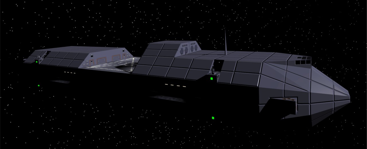
Tangent Space Specular Lighting
In my other objects (the Space Station and the fighter ships) I have used a specular map to determine the areas (mostly windows) in the texture that should have specular highlights from the sunlight. I have calculated the specularity amount in the vertex shader (as that requires the use of the pow function, which is rather slow). However, that meant that any specular highlights can never occur between any vertices. This was fine for windows and other such small flat areas. I also used the same system in the fighter ships, as those are pretty small. However, in order to get nice looking specular highlights for my Cruiser, I had to move the specular highlight calculation to the fragment shader.
In my original vertex shader code, I had calculated the specular color component for each vertex like this:
    worldPos = mul(unity_ObjectToWorld, v.position);
    worldNormal = UnityObjectToWorldDir(v.normal);
    ...
    //------------------------------------
    // Precalculate the specular color (this method only suitable for small and flat polygons!)
    //------------------------------------
    float3 halfVector = normalize(_WorldSpaceLightPos0 + normalize(_WorldSpaceCameraPos - worldPos));	// In world coordinates
    o.specular = _LightColor0 * pow(DotClamped(halfVector, worldNormal), 100);
I performed the calculations in world space, as Unity provides the _WorldSpaceCameraPos uniform automatically.
In order to move the calculation into the fragment shader, I would need to provide the input to the pow
function to the fragment shader. I did not want to add several new interpolators to send the world-space
vertex positions and surface normals to the fragment shader, so could I do the calculations in tangent space,
as I already had both the tangent space normal and tangent space light direction in my fragment shader?
To be able to do all the calculations in the fragment shader and in tangent space meant that I needed to provide it with the tangent space camera direction. Unity only provides world space camera direction, and even object space coordinates need to be specifically rotated to tangent space. This is too much work to do in the fragment shader, but as I already had the object-to-tangent-space rotation matrix available in the vertex shader, I decided to provide an object space camera direction as a uniform vector from the C# code to the vertex shader. I can then use the same matrix to rotate the camera direction as I use to rotate the object space light direction. I then replaced the specular item in my fragment shader input with this tangent space camera direction:
    //------------------------------------
    // Calculate the specularity camera direction in tangent space.
    //------------------------------------
    float3 camVect = _ObjCameraPos - v.position;
    o.specular = float4(mul(rotation, normalize(camVect)), 0);
I then moved the original code from the vertex shader to the fragment shader:
    fixed3 halfVector = normalize(i.lightDirection + i.specular.xyz);	// In tangent space coordinates
    col = sunLight + sh * _LightColor0 * pow(DotClamped(halfVector, tangentSpaceNormal), 100);
This worked pretty well, until I realized that when I moved further away from the ship, weird artifacts began to appear in the specular highlights, as in the following image:
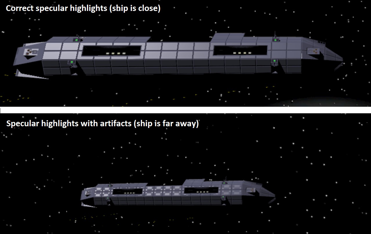
I immediately thought that this might be caused by some texture compression artifacts. After some studying the problem, it seemed that actually the mipmap levels cause this problem to appear. It is not even the specular map texture that causes this, but the normal texture! I tested forcing the texture not to use mipmap levels, and that got rid of the problem, but I don't think that is a good solution, as that can cause texture flickering. Perhaps I could somehow interpolate between using the normal texture, and just plain surface normal?
I spent some time thinking about how could I get the plain polygon surface normal into my fragment shader, until I realized what a stupid question that is! I am in tangent space, which by definition means that the polygon surface normal points to (0,0,1)! So, what was left was just to figure out a way to switch between the tangent space normal from the normal map, and the plain polygon surface normal, depending on the distance of the ship.
I already had all the data available, I just adjusted my vertex shader code to also send a value telling the ship distance (I determined on the Gear VR that the distance where the artifacts begin to appear is around 100 meters). Thus, I changed the vertex shader code to look like this (I just manually "normalize" the vector, so that I can use the length-based value as the fourth component of the vector):
    //------------------------------------
    // Calculate the specularity camera direction in tangent space.
    // Also determine the distance from the camera, to determine whether to use
    // normal-texture-based specular highlights (when close) or just surface-normal-based highlights (when far away).
    //------------------------------------
    float3 camVect = _ObjCameraPos - v.position;
    float camDist = length(camVect);
    o.specular = float4(mul(rotation, camVect/camDist), saturate((camDist-70)/50));
To take advantage of this distance value, I added just a single line into my fragment shader:
tangentSpaceNormal = lerp(tangentSpaceNormal, fixed3(0,0,1), i.specular.w);
After all these changes, I realized that I don't actually need the world space vertex position or normal
for anything in my vertex shader! I removed those (and changed the remaining code that used them to use
the tangent space values), and got a nice performance boost for my vertex shader! If you remember from
above, my vertex shader used to have 62 arithmetic and 27 load/store operations. These both dropped down
considerably, mostly because I did not need to use the unity_ObjectToWorld matrix at all anymore!
The resulting vertex shader only uses 22.5 arithmetic cycles and 22 load/store cycles per vertex, which
is pretty good, considering all the shadow plane handling.
  11 work registers used, 8 uniform registers used, spilling not used.

                          A       L/S     T       Bound
  Instructions Emitted:   40      22      4       A
  Shortest Path Cycles:   22.5    22      4       A
  Longest Path Cycles:    22.5    22      4       A
The fragment shader sadly got a bit slower again, but on the other hand not any slower than what it was
when I started improving it. However, the original code used 18 arithmetic operations totaling 6.5 GPU
cycles, while the new code uses 14 operations to spend the same amount of cycles. This shows how the
pow operation really has an effect on the performance.
  5 work registers used, 1 uniform registers used, spilling not used.

                          A       L/S     T       Bound
  Instructions Emitted:   14      5       2       A
  Shortest Path Cycles:   6.5     5       2       A
  Longest Path Cycles:    6.5     5       2       A
One weird thing about those results was that I have thought the shader has only 8 work registers available in the
vertex shader and 4 in the fragment shader, as I have usually always gotten spilling active when the work register
count would exceed that. This time both of the shaders use more work registers than that, but still don't need spilling.
Perhaps I was wrong about those limits, or perhaps this time the shader can use half-resolution work registers smarter.
PDC work
After I got the Cruiser model itself mostly done, I started figuring out how to handle the PDC guns. I wanted to have all the guns individually targeting enemy ships, and shooting streams of bullets, just like a real minigun. I went back and forth between having separate game objects for each gun, or having the guns be a part of the main Cruiser mesh, and dynamically updating the mesh when the guns move. Both of these have their own advantages and disadvantages, and I was not sure which system would be better. In the end I decided to at least experiment with having the guns be a part of the main Cruiser object, so that I can save on Draw Calls and can easily get the shadows to affect the guns as well. Since my shadow system cannot handle shadows from moving parts, I decided to not even attempt to have the guns cause shadows. Instead, I added spot lights to the gun recess back wall, which shines a light towards the PDC base. This should fool the eye, so that the guns not causing shadows is not as noticeable.
The first step was to model the PDC gun. It should have six barrels, which I planned to handle using a texture, so that I used just a six-segment cylinder as the barrel. The rest of the gun is just a simple box, and as I realized each corner of a box needs to have triple vertices in Unity for the three normal directions anyways, I decided to have rounded corners in my box. This creates no additional vertices, so it is a free visual quality improvement. I created a simple model in Cinema 4D, and then added those vertex positions into my MeshPostProcessor code, so that it can append the original Cruiser mesh vertex list with the vertices for all the PDC guns. This way I could easily find the correct vertices on the fly when I needed to orient the gun towards the target.
Each gun turned out to need 44 vertices (in Unity). The box needs 8*3 vertices, the barrel takes 7*2 (6 corners plus a duplicate for the UV seam), and the muzzle the remaining 6 vertices. Next, I generated a list of normals and tangents for these vertices. It is a bit annoying that I need to update also the normals and tangents when I update the vertex positions, but that can't be helped when I want to use a normal texture for some surface details, especially on the gun barrels.
Now that I had the vertices (and normals and tangents) set up, I began figuring out how to move them. In my original LineWars II, I used a system where I only rotated corners of a box, and then calculated the positions of the ship vertices using simple arithmetic, like mirroring or averaging the position. I decided to try something similar with the PDC vertex moving, so that I can avoid as many of the somewhat expensive rotation operations as possible. The first step was to determine where the PDC should point at, with a code like this:
    Quaternion rot = Quaternion.LookRotation(canShoot ? pdcDir : (left ? Vector3.left : Vector3.right), up ? Vector3.up : Vector3.down);
    Quaternion want = Quaternion.RotateTowards(dirs[i], rot, 180 * Time.deltaTime);  // 180 degrees per second rotational speed
Everything here is using local coordinates of the Cruiser. The helper variables I use are:
- canShoot is a Boolean determining whether a target is visible to this gun. Each gun has a certain sector where it can point at.
- pdcDir is a Vector3 giving the direction towards the target we want to shoot at.
- left and up are Booleans telling whether this is the left (or right) PDC, and up (or down) PDC.
- i is the loop index, as I go through all eight guns in a for loop.
- dirs[i] is a Quaternion telling the current rotation of this PDC.
Now we have the Quaternion telling us where we want to point at during this frame. I then calculate the new positions for the 12 vertices at the back of the ammo box, and for the 6 vertices at the back of the barrel, using code like this:
    // Fully rotate only those vertices whose positions we can't figure out from the other vertices.
    // Ammo box rear and rear ring
    for (int i = 0; i < 12; i++)
        verts[vi + i] = rot * PDCVerts[i] + pos;
Here the variables are:
- verts[] array contains the vertices of the Cruiser Mesh.
- vi is the vertex index of the first vertex of this PDC gun within the array.
- rot is the want rotation from the previous code (as this code is in a separate subroutine).
- PDCVerts[] array contains the vertices of the PDC, around the coordinate system origin, so they can be easily rotated.
- pos is the position of this PDC relative to the Cruiser Mesh origin. I translate the vertices to their correct position after the rotation.
For the normals and tangents I do something similar, with the difference being that there are only 4 distinct normal directions I need to rotate (up, right, and two barrel normal directions). I already have the Z-aligned unit direction, so these can handle all the normals. The tangents are even simpler, as every direction I need for the tangents has already been rotated for the normals, so it is just a matter of storing the correct directions to the tangent array.
So, what sort of a performance does my PDC vertex rotating system have? I added my usual System.Diagnostics.StopWatch-based system to count how many stopwatch ticks my routine takes. Looking at the results, the most common value was 460 ticks (with a single enemy flying around, so usually just two guns are tracking it). This was not terrible, but I thought there might be ways to speed this up further. I checked where most of the time is spent, and it turned out that the slowest operation is actually the setting of the Mesh vertices, normals and tangents. I first thought that perhaps I could do this only every second frame, but instead it occurred to me, that perhaps I don't need to move the guns every single frame, especially if the target direction has not moved much. I experimented with various angle limits, and came up with an angle limit of 4 degrees. If the target is less than 4 degrees away from where the gun is currently pointing, I skip moving the gun. This angle is still small enough to not be noticeable, yet it provided a nice performance boost. After this change, the most common stopwatch ticks value was 130 ticks, so much better than the original 460 ticks. Obviously whenever any of the guns actually needs to rotate, the code takes around that 460 ticks to handle it, but this does not need to happen every frame any more.
Okay, now the guns rotate and track targets, but I still need to make them shoot. For the bullets I created a pool of GameObjects using a LineRenderer. When a gun wants to shoot, I then get a free GameObject from this pool, set its position, and store the bullet direction into an array. I created a new ShootPDC() routine for this, and then added the following code to transmit the correct bullet start position to the routine:
    ShootPDC(new Ray(data.gameObject.transform.TransformPoint(pos + dirs[i] * new Vector3(0, 0.5f, 2f)),
             data.gameObject.transform.TransformDirection(Quaternion.Lerp(rot, want, Random.value) * Vector3.forward)));
Here I use some random linear interpolation between the actual target direction (rot) and the direction where
the gun is currently pointing at (want) to create some variation to the bullet directions. This way all bullets
do not follow the exact same route, especially when the gun is currently rotating.
I then added code to move the bullets. I decided to start experimenting with a bullet speed of 300 m/s (around the speed of sound, or 1000 km/h), as I want to have these bullets move much slower than my laser blasts (which move at something like 2000 m/s). I also decided to have a range of 1000 meters for the bullets, so each bullet stays alive a bit over 3 seconds. In my first tests I had 200 simultaneous bullets moving, but it looked like the guns ran out of bullets pretty often when running in the editor (with something like 400 fps frame rate), so I upped this to 400 bullets. I thought this was a good amount to test with, as obviously the bullet moving code should be really fast and efficient.
In my first test I had made a mistake with the material handling, and accidentally created a new material instance for every bullet, which made all the bullets have their own Draw Call! I quickly fixed this, and it was fun to see in the statistics window how it showed things like "Saved by batching: 395" and such. So, it looks like the LineRenderer can batch the lines pretty efficiently. I also used only a single LateUpdate call that moves all the bullets, as having every bullet have their own LateUpdate() routine would certainly be much less efficient.
I again turned to the StopWatch to see how much time moving all 400 bullets takes. It turned out to take around 3400 ticks, when using local coordinates and using transform.Translate() to move the bullets. I next tested without calling Translate, as I had read it is slower than simply adding the coordinates, and sure enough, the time dropped to 3100 ticks. I then thought that perhaps switching to world coordinates (LineRenderer.useWorldSpace = true) would be a smart move, in case that makes it simpler for Unity to calculate all the vertex positions when batching my bullets together. This turned out to increase the time to 3300 ticks, though. I then added code to use arrays to store the positions (instead of setting both start and end position separately), and this change dropped the time to 2500 ticks. I then converted the data for each bullet to a simple class, so that I can just have a single array of these classes to handle in the movement code. This dropped the time to 1750 ticks! This was reasonably good, considering that 400 simultaneous bullets should be pretty rare in the actual gameplay, it happens only in the editor. However, I still had no code to check if the bullets hit anything!
So, to check for the bullet hits, I needed to have some kind of a collision detection for every bullet. This sounded pretty difficult to get working efficiently, so I thought about what is the simplest collision detection I could use. I decided to have each bullet know the target it was aimed at, and only check collisions with this ship, and the viewer ship (as it would be quite distracting to have bullets go through your own ship without collisions). This creates a potential situation where bullets can go through ships or asteroids, but I will need to test this in actual missions to see how distracting it is. With a collision test (just a simple shield hit sphere) against both the target and the viewer ship, the time spent into the bullet movement routine increased to around 2750 ticks. This was in the situation where every bullet flies the full 1000 meters without hitting anything, so all 400 bullets are moving and testing for collisions every frame. This is not horrible, but it would be nice to get this running faster. I can of course do some trickery like not testing for collisions every frame, or precalculating situations where collisions cannot occur (like my ship is behind the turret and moving slower than the bullets), but I'll leave that for later.
There was still one issue with the bullets when the guns shot at moving targets: The bullets never seemed to hit the target! This was because the guns aimed directly at the target, not to where the target would be when the bullets would reach it. I thought this needed fixing, so I added simple code that attempts to aim at where the ship might be when the bullets reach it. There are probably more accurate methods for calculating this, and I might revisit this in the future. This simple code already solved the most of the problem, now most of the bullets hit the ship (as long as the ship moves in a straight line), which is pretty realistic.
    pos = enemies[j].gameObject.transform.position;
    float dist = (pos - data.gameObject.transform.position).magnitude;
    pos += enemies[j].gameObject.transform.rotation * new Vector3(0f, 0f, enemies[j].CurSpeed * dist / PDCSPEED);
    enemyLocalPos[j] = data.gameObject.transform.InverseTransformPoint(pos);
Here the variables are:
- enemies[] array contains a list of up to 4 close enemy targets this Cruiser is tracking. This is set up in the main collision detection routine, as it checks all ships against every other ship anyways.
- j is index to this enemy table.
- PDCSPEED is the speed of the bullet, currently 300 m/s.
- enemyLocalPos[] array stores the target local coordinates, so that the PDC guns can choose targets that are visible.
After all that code my PDCs tracked and shot at the enemy ship pretty convincingly, the only thing that was missing was some trick to make the barrel look like it is rotating. Since I already have a section of my ship texture atlas set aside for animations, I thought I'd experiment with an animated texture for the gun barrel. I used a YouTube video of someone shooting a minigun as a reference, and tried to emulate the red-hot glowing barrels and the flickering barrel rotation. I had already created a stationary texture, for the barrels, so I just copied that, shrinked it down somewhat (as my animated textures use only 64 texels per frame horizontally, and I want to use as few texels vertically as possible), and shifted the texture every second frame. This already looked surprisingly good, so I went a step further and added six different texture states (as each barrel takes 3 texels, and I emulated some half-steps as well). Sadly my 32-frame animation is not divisible by six, so there is a slight jump once per 32 frames. However, I don't think this matters, as it is supposed to look like a flickering rotation. The end result was pretty good, in my opinion! Especially considering that this barrel rotation takes no CPU time, and very minimal GPU time.
|
Here on the left is an animated GIF image showing the right side top PDCs of a cruiser tracking and shooting at an enemy fighter. The guns return to their rest position whenever they lose track of the target, and they also start shooting only after they have rotated close enough to the target direction. I might still add a proper muzzle flash, but on the other hand you rarely see the PDC guns this close in the game, so that is probably not needed. |
Aug 17th, 2018 - Collision Detection and Other Progress
The main focus of this blog post is my collision detection system. I had been somewhat scared of tackling that, as I assumed I would need to study a lot of difficult algorithms and such. It turned out not to be such a major issue after all, but more about that later on in this blog post. Before I worked on the collision detection, I worked on various other aspects of my game, so I'll start with those.
More Sound Effects
After writing the previous blog post I began adding some sound effects to my game. I first searched for some explosion sound that I could attach to the new explosion animation. I found Boom by Redbulldog98 and Distant explosion by juskiddink on freesound.org, and mixing those created a pretty good ship explosion sound. I had already used Rumbling Rocky sound by Opsaaaaa as the sound effect for when the asteroid crumbles. Next, I added a sound effect for when a laser hits a ship's hull, that I got from FUN-EXPLOSION02 by newagesoup. I just shortened the effect somewhat so it is more of a quick hit. It took me a while to find a suitable effect for a laser hitting the ship shield, but I finally decided to use SRSFX_Electric_Hit by StephenSaldanha. For the laser sounds I use JM_NOIZ_Laser 01 and JM_NOIZ_Laser 02 by Julien Matthey, one for the player's ship and one for the other ships. That took care of the most essential sound effects, but I still need quite a few effects for various other things.
Missile Handling
Next, I decided to add missiles into my game. Since the missiles are very fast and rather small, you mostly only see them as a few pixels on the screen, so I wanted to make them very low-poly objects. It only took me a little while to model the mesh in Cinema 4D, using a cylinder primitive and making a few adjustments to it. It was a simple thing to texture this as well, as I did not need any damage states. If a missile gets hit by a laser, it simply explodes immediately, there are no damage states as such. So, it only took me one day to model, texture, and code all the missile-specific stuff into LineWars VR. The missile mesh contains 82 vertices and 64 triangles in Unity, and looks like the following image. I only used a tiny 40 by 40 texels texture area for all the textures of the missile, so the texture looks quite blurry. That does not matter in the actual game, though.
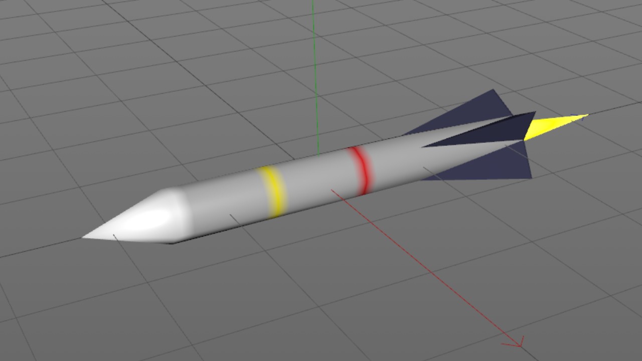
Upgraded to Unity 2018.2
One morning I got a Unity popup recommending me to upgrade to 2018.2 from my 2018.1 version. These upgrades are somewhat annoying, as the Unity people seem to always introduce some code-breaking changes in new versions. I decided to upgrade anyways, as I am still far from getting my game close to release, and just one-point level upgrade should not cause significant problems.
It took me about a whole day to get my game to compile using the new version of Unity, though. The first major issue was, that I needed to upgrade to a newer Android SDK. However, when I tried to let Unity upgrade the Android SDK, I got this:
CommandInvokationFailure: Unable to update the SDK. Please run the SDK Manager manually to make sure you have the latest set of tools and the required platforms installed.I then tried to upgrade the SDK manually, but this also ended up in an error:
Warning: An error occurred during installation: Failed to move away or delete existing target file: C:\Projects\AndroidSDK\tools
Move it away manually and try again..
This was a bit silly, as the sdkmanager.bat which performs the upgrade sits in that directory, so of course it cannot be moved away or deleted! I found a Stack Overflow question about this specific issue, and using the recommendations there I managed to get the SDK upgraded.
The next problem was that almost all of my shaders failed to compile, with error messages like the following:
Shader error in 'LineWarsVR/CruiserShader': invalid subscript 'instanceID' 'UnitySetupInstanceID': no matching 1 parameter function at line 60 (on gles3)This was not much of an issue, as I don't actually use or need instancing in any of my shaders, that was just a left over from some tests I had made earlier. I commented out all UnitySetupInstanceID() calls from my shaders, and got them to compile.
I then tested building the executable for Android, but that complained about missing passwords. It took me a little while to remember that I had tested uploading my game to the Oculus Store Alpha Channel some time before, and had to add a new key store with passwords for that. It looked like Unity does not remember these passwords, so I need to give them again whenever I build a new binary for my phone. Not a big deal.
The final issue, again a result for that Oculus upload, was that I needed to replace INFO with LAUNCHER in the AndroidManifest.xml to get a standalone executable to work. I need to remember to switch this back to INFO when uploading a new version to the Oculus store.
Purchased InControl
As I want to support various gamepads with LineWars VR, I had been thinking about how best to handle this. I had read from the "Endspace" developer blog that they use InControl for this. I thought it should probably work well with my needs as well, and decided to purchase it. It was only $35 in the Unity Asset Store, even though the main page says it costs $40, so I thought that was a good deal. I had some issues making it work properly with my Snakebyte VR:CONTROLLER, but after testing my controller with Endspace, I noticed it behave exactly the same. Looks like the problem is in the controller itself, it just does not seem to always recenter the analog sticks properly when you release them.
Anyways, I added quick code to read the InControl controller positions, and it seemed to work fine. It still needs a lot of fine-tuning and such, and I also need to handle multiple scenes better, add configuration page, and so on. It does look like I can let InControl worry about the different gamepads and just focus on the game myself, which was exactly the reason why I purchased it.
Collision Detection
Okay, now let's get into the main feature of this blog post, my collision detection algorithms. As I have mentioned before, I don't want to use the Unity's built-in physics module with its Collider objects, as these are black boxes and I believe I can program a more performant system for the specific needs of my game. In the original LineWars II I had simple bounding spheres that I used for collision detection, but in LineWars VR I wanted to have more accurate collision. I wanted to use mesh-based collisions, but still keep the performance high. This sounded like a pretty difficult problem, and thus I had assumed it would take mew a few weeks to get this done.
The first step of any collision detection is of course trying to preprocess the situation using some fast code to detect if a collision is at all possible. Since all my objects already have bounding spheres, which correspond to the distance of the furthest vertex from the object center, the first step was to detect if the bounding spheres intersect. This is the simplest collision detection there is. You just need to calculate the distance of the sphere origins, and subtract the sum of the sphere radii from that. This is faster to calculate using the squares of both of those, so you can avoid the square root. This way I can quickly determine which objects cannot collide during this frame.
I added a new collision detection routine call into my MoveShips() routine, which handles the movement of all the ships. I use a single routine to handle all the ship movements instead of having each game object having an Update() routine separately. This is closer to how my old LineWars II was built, and I wanted to use a similar system. Thus, I can also have a single CollisionDetect() routine that handles all the collisions. Into this new CollisionDetect routine I then added two for-loops, so that each ship is tested against all the lower-indexed ships within my ShipData array. If a ship has died, it's ShipType enumeration value gets changed to NotExists, so I am using that to determine which ships are still alive. So, the main structure of my collision detection routine became this:
    // Check each ship against all the lower-indexed ships for collisions
    for (int i = 1; i < ShipCount; i++)
    {
        ShipData dataA = ShipParams[i];
        if (dataA.ShipType == ShipTypes.NotExists)
            continue;
        Vector3 posA = dataA.gameObject.transform.position;
        for (int j = 0; j < i; j++)
        {
            if (dataA.ShipType == ShipTypes.NotExists)  // In case shipA already collided with a previous ship and died...
                break;
            ShipData dataB = ShipParams[j];
            if (dataB.ShipType == ShipTypes.NotExists)
                continue;
            Vector3 posB = dataB.gameObject.transform.position;
            // Check a potential collision between dataA and dataB
            float shieldDist = dataA.ShieldRadius + dataB.ShieldRadius;
            shieldDist = shieldDist * shieldDist;   // Use the squared min distance
            Vector3 posB = dataB.gameObject.transform.position;
            Vector3 vectAB = posB - posA;
            // If the encapsulating shields don't intersect, the objects have not collided.
            if (vectAB.sqrMagnitude > shieldDist)
                continue;
        }
    }
If the shields of the objects ("shield" meaning the bounding sphere for objects that do not have shields) intersect, then it is time to check whether the actual object meshes intersect. This mesh versus mesh intersection is a rather complex operation. I studied the code for "Fast Collision Detection of Moving Convex Polyhedra" by Rich Rabbitz from "Graphics Gems IV" for a while, but thought that it was too complex for my needs. I would have needed to build a new structure for each of my objects to use that algorithm, but I would rather not do that, as I already have a K-d tree (as mentioned in my Apr 21st, 2018 blog post) for each of my objects to speed up the laser hit collision detection. Wait a minute, I already have a special structure for a certain type of collision detection, could I perhaps use that also for the ship versus ship collisions? My laser hit test uses the KDtree of an object to quickly determine which triangles of the mesh are within the partitioned bounding box where the laser ray may hit the object, and then does a ray-triangle intersection test for only these triangles. If I could somehow make the ship collisions behave like a ray-triangle collision, I could use the same system for these.
The collisions that I needed to handle were the collisions between the fighter ships, a collision between a fighter ship and an asteroid, and a collision between a fighter ship and the space station. Collisions between an asteroid and a space station are handled specially in the first mission of my game, and in other missions the asteroids do not move. Then I would also need to check collisions against the cruisers and the alien motherships, but I decided to leave those out for now. So, could I somehow make my fighter ships behave like a laser ray?
I noticed that my ray-triangle intersection algorithm does not actually care about whether the ray goes forwards or backwards. So, I could actually have an object partially penetrating a triangle of another object, and cast a ray from the penetrating part of the object backwards. Since my fighter ships all have pointy noses and always move forwards, I thought the nose would be a perfect starting point for a "collision ray". My fighter ships even have simple shapes, for example the Pirate fighter is basically just an elongated tetrahedron, so I could handle its shape pretty simply just by sending three rays from the nose towards each of the three rear corners. The Cobra ship is not much more complex, I could handle it using four rays, from the nose to each wing tip and to top and bottom. Then I just needed to check whether the ray-triangle hit position along any of these rays is less than the length of the ship away from the nose! Here below is a picture showing the three "collision rays" of a pirate ship. They do not obviously exactly follow the mesh shape, but they are quite accurate enough for collision detection of fast moving ships.
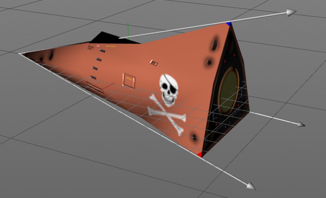
So, I added some static variables to contain the rays of the Pirate and Cobra ships, and then created a routine that tests these rays against the KDtree of the target object. Here below are the parts of the routine that handle the Pirate ship. The Cobra part is similar, it just has four rays instead of three.
    private static Ray[] PIRATERAYS = new Ray[] { new Ray(new Vector3(0f, 0f, 9.14231f), new Vector3(0f, 0.25027f, -0.96818f)),   // nose to vertical stabilizer tip
                                                  new Ray(new Vector3(0f, 0f, 9.14231f), new Vector3(0.21404f, -0.15747f, -0.96405f)),   // nose to left wing tip
                                                  new Ray(new Vector3(0f, 0f, 9.14231f), new Vector3(-0.21404f, -0.15747f, -0.96405f)) };   // nose to right wing tip
    private static float PIRATERAYENDZ = -6.62195f;  // Z coordinate of the rear wall of the ship

    private static bool ShipMeshHit(ShipData ship, ShipData target)
    {
        Vector3 hitPos;
        int hitTri = -1;
        bool hit = false;
        Transform st = ship.gameObject.transform;
        Transform tt = target.gameObject.transform;
        // Translate the ship "collision rays" into target local coordinates, and use KDHit test to determine if they hit.
        Ray localRay = new Ray(tt.InverseTransformPoint(st.TransformPoint(PIRATERAYS[0].origin)), Vector3.zero);
        for (int i = 0; i < PIRATERAYS.Length; i++)
        {
            localRay.direction = tt.InverseTransformDirection(st.TransformDirection(PIRATERAYS[i].direction));
            hitPos = Vector3.zero;
            if (target.KDTree.KDHit(localRay, ref hitPos, ref hitTri))
            {
                // Check where the hit position is along the "collision ray". The "hitPos" is in the target's coordinate system.
                Vector3 localHitPos = st.InverseTransformPoint(tt.TransformPoint(hitPos));
                if (localHitPos.z >= PIRATERAYENDZ)
                {
                    // The target ray hit position is within the ship mesh, so this is a proper collision!
                    Ships.Collision(ship, localHitPos, -1); // Call the ship's collision handler
                    hit = true;
                    break;
                }
            }
        }
        return hit;
    }
The Ships.Collision() routine then tests whether the ship has enough armor health left that it survives this frame of the collision,
damages the armor and possibly some equipment, reduces the speed of the ship, and possibly explodes the ship if the accumulated
damage exceeds the survivable amount. The above routine also handles similar stuff for the collision target object, I left that
part out of the above routine for clarity.
There is still one extra step in my collision handling routines, specifically for the Space Station. It has such a complex shape, that I thought running the full KDTree hit test whenever a fighter ship is within the bounding sphere of the station is unnecessary work. Since I plan to always orient my space stations along the world Z axis, I could do some collision prefiltering before calling the KDTree hit testing. I separated the space station into sections along the Z coordinate, so I could easily determine which part of the station a ship could hit. For example, if the ship's position has a negative Z coordinate less than the station's lowest Z value minus the ship's shield radius, the ship cannot hit the station even though their spheres may intersect. Similarly, since the station main drum has a radius of 55 meters, if the ship is sufficiently far in front of the station that it cannot hit the habitation ring or its poles, and the ship's xy-distance from the station center is more than 55 meters plus the ship's shield radius, it cannot collide with the station even when it is inside the space station's bounding sphere.
I tested the performance of my new code using the "Demo" mission of my game. In this mission six Cobra fighters (plus the player) attack an enemy space station (or "star base" as it is called within my game) which launches several Pirate fighters to defend it. When the mission begins and there are 7 friendly ships, one space station, and 10 asteroids, the collision detection routine runs at about 500 Unity editor stopwatch ticks per frame. When most of the ships are dead, this drops down to around 100 stopwatch ticks, and the worst case seems to be somewhere around 1500 stopwatch ticks. I have learned that everything below about 5000 stopwatch ticks for such a once-per-frame routine is acceptable and does not cause framerate hiccups. So, my routine should be quite performant enough, and if it turns out to be too slow for really massive battles (my goal is to have up to 50 ships in a battle), I can always split the code to only handle half the ships per frame, alternating between which halves are handled. I actually had to do this for my LineWars DS version for Nintendo DS, as that handheld console has quite a weak CPU.
Space Station Collision Damage
After the main collision detection routine was done, I started working on what happens with the Space Station when it gets hit by a moving ship. I had already worked on some laser hit damage states before, and I decided that as a result of a collision, the adjacent panels of the station shall go directly to the most damaged state (which usually is the fire animation). I just need to check which is the closest vertex of the collision, and make all the panels sharing this vertex location go into the most damaged state. There are a lot of panels on the space station, and I need to manually set up all the UV coordinates for each of these damage states, so this is a lot of work. I had gotten wiser when I made the fighter ship damage states, and simply used U offset to determine the damage state, but the space station was my first model with damage states, and I hadn't thought about the amount of work these damage states require when I originally made it. I just need to work on it for a few days every now and then to get it eventually done. It is too boring a chore to do in one go.
|
Here on the left is an animated GIF image showing two Cobra fighters chasing a Pirate fighter and forcing it to crash into the habitation ring of the Space Station. The Pirate ship's shields flash red during the initial contact with the habitation ring, and the shield hit tries to bounce the ship away from the station. Due to the high speed of the ship, it only takes a couple of frames until the actual ship (or rather one of the "collision rays") also penetrates the station, causing the ship to explode. The collision handling also causes damage to the space station. Only the lower deck of the habitation ring currently gets damaged, as the upper deck still lacks the damage states. |
MeshPostProcessor for Space Station
While I worked on the damage states, I noticed that one panel on the Space Station had slightly wrong UV coordinates. I fixed these, but then noticed that the procedural shadow system stopped working properly, there were some extra shadows in front of the habitation ring poles. This reminded me, that I had used such non-continuous UV coordinates to force Unity to duplicate the vertices of these panels, to separate the shadowed parts from parts of the station that have no self-shadowing. However, for the damage states, I needed the UV coordinates to be correct.
When I originally created the Space Station model and started texturing it, I was not aware of Unity's AssetPostprocessor component. Now that I had used it successfully to give all the triangles unique vertices for my fighter ships, I decided to use it also for the Space Station, to create unique vertices where needed. This way I could keep the UV coordinates correct.
I also realized, that my MeshPostProcessor is the correct place to add the Colors array to the Mesh. As I mentioned on my Mar 25th, 2018 blog post, I use vertex colors to let the shader know which part of the station (regarding the various shadow areas) this vertex belongs to. I had used the scene Awake() method to call a routine to calculate this whenever a mission begins. However, it would be much more efficient to pre-calculate this while importing the Mesh itself, as this data never changes dynamically. Thus, I moved all my code to find certain polygons and give their vertices the correct color values into the MeshPostProcessor.
Pre-alpha Gameplay Footage
I meant to record some video about my new collision detection algorithms, but the clip I recorded actually shows quite a bit about the general gameplay of LineWars VR, so I decided to release it as a pre-alpha gameplay footage. Pretty much everything is still unfinished, but it has the most important gameplay elements in place. There are some frame skips in the video, which seem to be caused by the recording itself, as the actual gameplay in Gear VR even on my slow Samsung S6 phone is completely smooth.
That's about it for this blog post, thank you for your interest in my progress with LineWars VR!
July 22nd, 2018 - Mission One Playable and Ship Damage States
After writing the previous blog post, I worked a few days on the Pirate ship texturing and fixing a couple of bugs in my handling of a laser hitting an asteroid. I had noticed that sometimes the laser seems to not hit an asteroid, even though it should. This turned out to be a simple issue of my forgetting to clear one variable in the code. Another issue was that the NPC (Non-Player Character) controlled Cobra 2 ship continued shooting at something even when there were no more enemies. This was again a simple issue, I did not test correctly whether an enemy ship was still alive. After these fixes I thought it might be interesting to attempt to make the first mission actually playable.
Making Mission One "Asteroid Storm" Playable
The things I needed to do to make the first mission playable were the following:
- Have the asteroids around the starbase move towards the starbase.
- Detect a collision between an asteroid and the starbase. This determines whether the mission (saving the starbase from the approaching asteroids) has failed.
- Restart the level if the mission fails.
- Go to the next level (with more asteroids) if all the asteroids were destroyed successfully.
- If the most difficult level (level 10) was successfully handled, the mission is completed, and the player is returned to the main menu.
The second part was much more difficult. I did not want to use the Unity built-in physics system with its collision detection, as I am not sure about how performant it is. I believe I can tailor-made a more efficient collision detection system myself. In the most difficult level I have 46 asteroids all moving and about to collide with the starbase, with every asteroid consisting of 528 triangles. So those would need quite complex mesh colliders for accurate collisions, and I would still need to handle collisions between the two ships (player and the NPC helper) and all the asteroids. In addition to that, I would need collision detection between each of the asteroids, in case they hit each other before they hit the starbase. All this felt like something that could easily kill the performance of my game.
I began by studying the collision detection algorithms on the web, using the great Realtime Rendering reference page Object/Object Intersection. After a little bit of thinking about my specific scenario, I came up with an interesting idea to reduce the required computations by quite a bit. Since my asteroids move towards the starbase at a constant velocity, I could actually calculate beforehand the exact frame when the asteroid hits the starbase. I could even orient the asteroid so, that it hits with its farthest out vertex. Since the asteroid rotates at a constant angular velocity, I can have it be in a known orientation when it hits the starbase, and just calculate backwards the required orientation it should have when the level begins.
Thus, the only things I needed were to determine where on the starbase I want each of the asteroids to hit, and in what orientation they should be at that point. As my asteroids are procedurally generated using an FFD deformer, I just added code into the mesh generation routine to remember which vertex was the farthest out from the asteroid center. I stored this into "MaxShield" field of my common ship structure (as the asteroids don't have shields and I did not want to add a new field for just asteroids). I could of course convert my ship structure to a class and use proper class inheritance to handle specific needs of different ship types, but I wanted to keep things like that close to what I did in LineWars II (which was coded fully in Assembler language).
Anyways, the code to get the needed rotation of the asteroid given the vertex index is as follows. It uses the "MeshData" structure of the ship data "asteroid", which is simply a cache for the mesh triangles and vertices, so I don't need to access the actual Mesh object in my C# code.
    // Calculate rotation needed to point the farthest out vertex of the astroid toward the world Z axis
    Vector3 maxVector = asteroid.meshData.Vertices[asteroid.MaxShield];
    Quaternion rot = Quaternion.Inverse(Quaternion.LookRotation(maxVector));
I decided to have six different "hit locations" on the starbase where the asteroids could hit it:
- Outer rim of the habitation ring, which has an outer radius of 139 meters and width of 19 meters, at Z coordinate 0.
- Front wall of the habitation ring, at 134 plus or minus 5 meters radius, with Z coordinate at 8.5 meters.
- Back wall of the habitation ring, at 134 plus or minus 5 meters radius, with Z coordinate at -8.5 meters.
- Solar panels, of which there are four separate panels, each 44 meters wide and 84 meters long, with their back-side Z coordinate at -92.5 meters.
- Main body of the starbase, which has a radius of 55 meters.
- Front wall of the starbase, with the Z coordinate at 58 meters.
Here is an example of the calculations in the first section, outer rim of the habitation ring. I can have the asteroids star randomly around the ring, just making sure they start further out than the habitation ring. The code that handles this is as follows. Here "level" is the current mission level (1..10) and "asteroid.ShieldRadius" is the size of the asteroid, that is, the magnitude of the farthest out vertex vector).
    hitSeconds = Random.Range((float)(level + 21), (float)(level + 40 + 20*level)); // When the asteroid will hit the starbase
    Quaternion dirRot = Quaternion.Euler(0f, 0f, Random.value * 360f);              // Asteroid starting position around the world Z axis of the starbase
    // Starbase outer rim, end position along the rim outer edge (x=139 + radius, y=0; z=-60 +/- 8), rotated around z
    hitPos = dirRot * new Vector3(139f + asteroid.ShieldRadius, 0f, -60f + Random.Range(-8f, 8f));
    startPos = dirRot * new Vector3(Random.Range(200f, maxDist) + asteroid.ShieldRadius, 0f, -60f + Random.Range(-200f, 200f));
    hitRot = Quaternion.LookRotation(-hitPos) * rot;
The code above gives me location of the asteroid hitting the starbase, the asteroid starting position, and
the orientation of the asteroid when it hits the starbase. To keep things simple, I decided to use the same
orientation for both when the asteroid hits the starbase and when the mission starts, I simply make the
asteroid rotate random number of full revolutions on the way to the starbase. This random value is adjusted
by the asteroid size, so the smaller asteroids may rotate faster than the larger asteroids.
Okay, now I can handle the asteroids hitting the starbase, but how about asteroids hitting each other? Here I decided to make things easier for myself, instead of letting the asteroids hit each other, I decided to prohibit this completely. That meant I had to generate the starting positions for the asteroids in such a way that they do not hit each other on the way to the starbase. Here I used the Capsule / Capsule Collision detection algorithm, with the capsules corresponding to the routes the asteroids take when they move towards the base. As the asteroids may hit the base at different times, the capsules should only cover the routes where both the asteroids are "alive". I added a loop into the asteroid generation routine to check each new asteroid generated against all the other already generated asteroids, and retry the new asteroid starting position until the code finds a position where the asteroid does not hit any other asteroid on the way. This turned out to work fine, except that the code may take an extra second or two trying to find suitable starting positions for all the asteroids.
Okay, now I could detect the collisions simply by checking if the "hitSeconds" of any asteroid is less than the current time, and then call the "Mission failed!" stuff and restart the scene if so. However, it turned out that the time it took to generate the asteroids for the next level became annoyingly long in the higher levels, and thus I began looking into ways to restart the mission without the need to restart the whole scene. I decided to create all the 46 asteroids when the scene is started (for the first time) and cache the starting positions and orientations of all the asteroids. Then when the level is restarted or cleared, I simply reset the positions and orientations (and whether they are active or not) of all the GameObjects and continue the same scene. This meant that the level change is instantaneous, but the first level takes a little while to start up.
This pretty much made it possible to play the first mission of my game! I am still missing the ship/asteroid and ship/starbase collisions, most of the sound effects, etc., but the basic gameplay is in place, yay! I spent a couple of days adding a version of the asteroid shader which receives shadows from the starbase (for those asteroids that hit the shadow side of the base) and made a very simple deformation algorithm for the starbase to deform as it gets hit. The latter still needs quite a bit of work to look convincing, though.
Fighter Ship Damage States
After I got the first mission practically playable, I decided to work next on the fighter ship damage states. My plan was to have each triangle/polygon of the fighter ships have four damage states:
- Not damaged
- Laser scorched hull plating
- Structural damage. Hit to this level can damage some ship equipment (laser, shield generator, thrusters, etc.) located "underneath" this triangle.
- Major structural damage. If a triangle is already at this damage level and it gets hit again, the whole ship will explode.
I am using a shared 2048x2048 texture atlas for all my ships, including the starbase and the cruiser, so to hit several damage states for all of these ships into the same texture atlas meant that the texturing of the ships needs to be rather coarse. I decide to go with 256-texel wide damage state slots, so that I can easily just add 1/8 to the UV coordinates of the vertices of the triangle that gets hit, to go to the next damage state. I was able to fit the full textures of both the Cobra and the Pirate ships into a 256 by 550 texture area, so they only take a little bit over one eight of my texture atlas. As part of my texture atlas is reserved for animation, that meant that about 5/6 of the texture atlas can still be used for the starbase, cruiser, and the alien ship. I also need to fit the textures for the missile somewhere, but that should only take a very small part of the texture atlas.
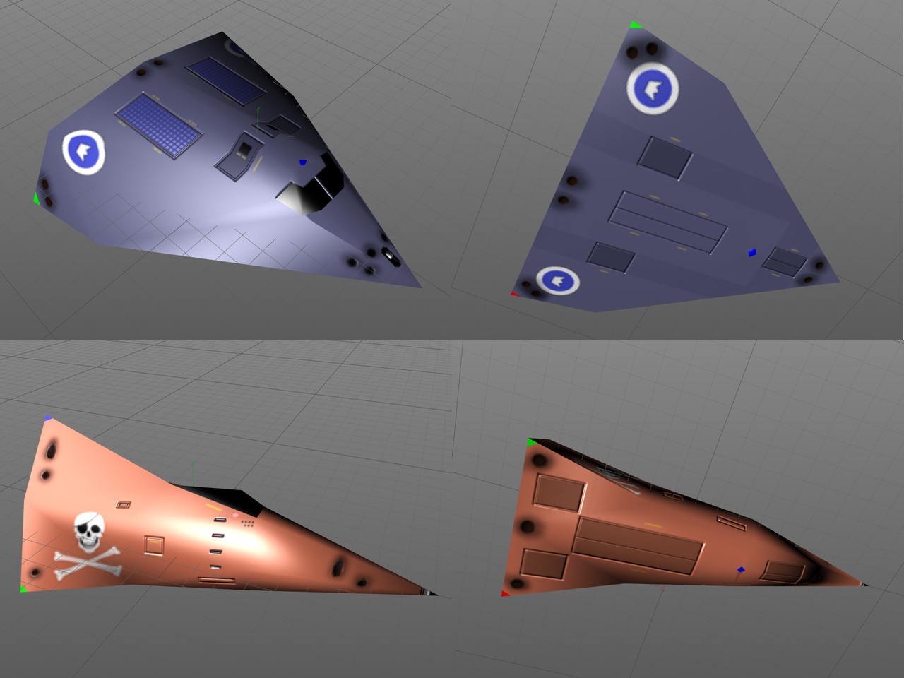
The images above are taken from Cinema 4D, which does not have all the surface normals quite as I wanted them, so I used my MeshPostProcessor to adjust some of the vertex normals (for example normals around the pirate ship bottom blue flash light, and the pirate ship nose vertex). The insignia of the Cobra ship is for the "Princess Royal Guard". I decided to use the Finnish Air Force blue/white roundel as the basis, and just replaced the inner white circle with a white crown. This is sort of like a "Royal Finnish Air Force" insignia, if Finland was a kingdom. :)
I pretty much suck at texturing in general, and damage texturing in particular, so it took me over two weeks trying to generate the damage model textures. I have not even managed to create the damage state textures for the rear of the ships, which are most likely to get hit, as I am still trying to figure out what the ship main thrusters should look like when they are damaged. Less bright light emissions at least, but I have not been able to decide what else is needed. I am not terribly happy with the other panels either, but at least they now have some semblance of damage.
Here below is a short YouTube video demonstrating the damage states of both the Pirate and the Cobra ships.
Explosion Footage
As I mentioned in my first blog post (at the end of this page), I had already back in the end of last year found some nice free explosion footage from Videezy, but the problem with that footage was that it did not have an alpha mask. I had been working on adding an alpha mask myself to that footage on and off for the past several months, but now finally I decided that enough is enough, I will need to purchase some proper explosion footage material. I searched the net, trying to find some ArtBeats reel footage, but it looked like ArtBeats does not sell footage directly to end users. The stock image sites that resell their footage did not clearly state whether the footage includes an alpha channel, and a single video seemed to cost between $35 and $80, which I thought was rather expensive.
After some more googling I found the ActionVFX site, which clearly stated that all files include an alpha channel, and the collection of ten aerial explosions cost only $50 at full HD resolution. I thought that was a pretty good deal, especially since the license allows you to use the footage for practically everything you can think of, so I purchased that collection. I downloaded the collection in ProRes format (not knowing what that format was), and then began to study how I could convert that ProRes-format MOV file into something useful for my game.
It turned out that FFmpeg can read ProRes files, so I decided to use my trusty AviSynth plus VirtualDub software combination to create a set of RGB frames and a set of Alpha frames from one of these explosion clips.
LoadPlugin("C:\Program Files (x86)\AviSynth\plugins\ffms2-2.23.1-msvc\x86\ffms2.dll")
v = FFMpegSource2("Aerial_Explosion_5_0783_2K.mov") # 310 frames, fire done at frame 120, slow dissolve
s = v.SelectEven().AssumeFPS(30)                    # Only take every second frame, assume the speed is still 30 FPS
v = s.Trim(0,63)                                    # Take only the first 64 frames
v = v.Crop(576,80,768,768)                          # Make the explosion fill the frame as fully as possible
v = v.Lanczos4Resize(256,256)                       # We want frames of 256 by 256 pixels
v = v.Fadeout(25)                                   # Fade out to black, during the last 25 frames
# Replace the above line with the following for the Alpha channel, otherwise the result is the RGB data.
#v = Overlay(v.ShowAlpha().Fadeout(30), v.ShowGreen().Fadeout(10), mode="add") # Have RGB data cause bumps to the Alpha fadeout
return v.ConvertToRGB32()
After that I just needed to combine the frames into an 8x8 sprite sheet, for which I used my CreateAnimBMP
Unity Editor helper script that I had created some time earlier. This script has the names of the first RGB image
and the first Alpha image, together with the output image name and the number of frames and output image size as
parameters. Then it reads the input images (both the RGB image and the Alpha image) for each frame and calls the
ProcessFrame method for each of these frames. This method stores each frame to the correct location of the
output byte array outbytes, which is then written into the output BMP file. The inoffs parameter is
the start offset of the RGBA data in the output BMP file, frameSize is the resolution of the single frame (256),
and oSize is the resolution of the output file (2048).
    private void ProcessFrame(int frame, byte[] outbytes, byte[] rgbbytes, byte[] alphabytes, int inoffs, int frameSize, int oSize)
    {
        // BMP pixel format = Blue, Green, Red, Alpha
        // Y coordinate goes from bottom towards the top, so swap the y offset
        int xoffs = 4 * (frame % (oSize/frameSize)) * frameSize;
        int yoffs = ((oSize/frameSize) - 1) * 4 * oSize * frameSize - 4 * (frame / (oSize/frameSize)) * (oSize / frameSize) * frameSize * frameSize;
        Debug.Log("frame " + frame.ToString() + ", xoffs=" + xoffs.ToString() + ", yoffs=" + yoffs.ToString());
        for (int y = 0; y < frameSize; y++)
        {
            for (int x = 0; x < frameSize; x++)
            {
                outbytes[54 + yoffs + 4 * oSize * y + xoffs + 4 * x] = rgbbytes[inoffs + 3 * (y * frameSize + x)];
                outbytes[54 + yoffs + 4 * oSize * y + xoffs + 4 * x + 1] = rgbbytes[inoffs + 3 * (y * frameSize + x) + 1];
                outbytes[54 + yoffs + 4 * oSize * y + xoffs + 4 * x + 2] = rgbbytes[inoffs + 3 * (y * frameSize + x) + 2];
                outbytes[54 + yoffs + 4 * oSize * y + xoffs + 4 * x + 3] = alphabytes[inoffs + 3 * (y * frameSize + x) + 1];    // Use green channel of input
            }
        }
    }
This is an animated GIF showing this specific explosion, and I still have nine different variations that I can use for other explosions.
Previous blog posts
See here for blog posts from June 2018 and before.