
LineWars VR Blog Posts
June 19th, 2018 - Progress Report, Voice Acting
Cobra cockpit avatar
After working on the Cruiser bridge pilot avatar, which I wrote about at the end of my previous blog post, I started working on the pilot avatar for the Cobra cockpit. The differences between these avatars are the 18-degree tilt of the Cobra cockpit, and the fact that the Cobra cockpit has the joystick between the pilot's legs, while the Cruiser has the joystick on the right arm rest. It was more difficult than I anticipated to handle these differences.
The first thing I needed to do was to model a separate version of the hand holding the joystick. To optimize the mesh, I had removed all polygons that always face away from the camera from the original mesh, however, the Cobra cockpit has the joystick in a different orientation, so some of these removed polygons were suddenly needed. Luckily, I still had the original object saved away, so I could just copy back the needed polygons. This increased the vertex and polygon count, however, so I spent some time optimizing the mesh, to get down to around the same number of vertices is I had in the Cruiser joystick hand. I got down to 1239 vertices for the Cobra joystick hand, compared to 1233 vertices in the Cruiser joystick hand, so almost exactly the same amount.
Next, I added the C# code that updates the _JoystickProjMat matrix for the throttle and joystick hands, these were identical to the code for the Cruiser avatar. However, when adding the code for the lower arms, I ran into some issues. I realized that the code I used in my previous blog post to calculate the positions of the connected vertices was actually buggy, and just happened to work because all the objects shared the same orientation. Now that I had to add the 18 degrees tilt of the Cobra cockpit, my algorithm stopped working.
After some thinking about this problem, I realized that it would actually be smarter to use the same rotation matrix I use in the shader to do the inverse rotation in the C# code. I just need to invert the matrix. Thus, I created the following code, which does pretty much the same as the code in my previous blog post, but here both the handRot and armRot have an added 18-degree tilt added, and the vertex movement is done using a matrix multiplication.
    //------------
    // Adjust the vertex positions by the current throttle amount
    //------------
    // First calculate how much the whole lower arm should move.
    // It moves as much as the wrist moves because of the throttle rotation,
    // minus how much the arm rotates because of the elbow joint connection.
    Vector3 trans = s_CobraThrottleTrans;
    Quaternion handRot = Quaternion.Euler(myData.CurSpeed * 30f / myData.MaxSpeed - 15f - 18f, 0, 0); // Throttle hand rotation, only around X axis
    Quaternion armRot = Quaternion.Euler((myData.MaxSpeed * 3f / 4f - myData.CurSpeed) * 8f / myData.MaxSpeed - 18f, 5f, 0);   // Arm rotation
    Vector3 wristPos = (handRot * s_LLArmWristPos) /*- s_LLArmWristPos*/ - (armRot * s_LLArmWristPos) /*+ s_LLArmWristPos */;
    Matrix4x4 mat = Matrix4x4.TRS(trans + wristPos, armRot, Vector3.one);
    Matrix4x4 invMat = Matrix4x4.Inverse(mat);
    // Translate to the opposite direction and rotate the wrist connected vertices
    for (int i = 0; i < m_VertexData.Count; i++)
    {
        // First add the handRot rotation, and then remove the effect of the _JoystickProjMat rotation
        m_Verts[m_VertexData[i].idx] = invMat.MultiplyPoint3x4(handRot * m_VertexData[i].vertex + trans);
    }
    m_Mesh.vertices = m_Verts;
    // Lower arm rotation
    m_Mat.SetMatrix("_JoystickProjMat", mat);
I was able to use mostly similar code for all the lower and upper arm movements. The difference is in the armRot calculation, as especially the Cobra right upper arm needs to move in a rather complex way when the joystick moves around all three axes. It was much simpler to make work for the Cruiser bridge, so I decided to keep the joystick on the right arm rest for my third ship (the Pirate ship), which I haven't even started modeling yet. The Cobra cockpit shall be the only one with the joystick between the pilot's legs.
MeshPostProcessor
After adding the pilot avatar vertices and polygons to the CobraCockpitSwitches mesh (I use two separate meshes for the Cobra cockpit, CobraCockpit which contains all the straight panels and the switch legends and illumination, and the CobraCockpitSwitches mesh for all the switches and such. These meshes have different materials, and the mesh with the switches had a more suitable material for the pilot avatar. However, the size of the mesh grew to 11688 triangles, which I thought was too much.
I actually had already a while ago had an idea to code some sort of a postprocessor for my meshes, where all the polygons that always face away from the camera could be removed, and after that also all the unnecessary vertices could be removed. It would be a lot of work to do all of this by hand (as I currently have over 280 separate switches in the cockpit, all of which I combine into a single mesh when exporting the object from Cinema 4D to Unity). Instead of removing these back faces by hand, I decided to look into writing a small snippet of code to do that automatically.
I found a simple example for using the Unity AssetPostprocessor. This seemed to be the place to add the code to remove the hidden polygons and vertices from my CobraCockpitSwitches object. After some coding and debugging I was able to create an extension class that does what I needed. The code I came up with is as follows:
public class MeshPostProcessor : AssetPostprocessor
{
    void OnPreprocessModel()
    {
    }

    void OnPostprocessModel(GameObject g)
    {
        Apply(g.transform);
    }

    void Apply(Transform t)
    {
        if (t.name == "CobraCockpitSwitches")
        {
            Mesh mesh = t.GetComponent<MeshFilter>().sharedMesh;
            if (mesh == null)
            {
                Debug.LogWarningFormat("Failed to get mesh for object {0}!", t.name);
                return;
            }
            int[] tris = mesh.triangles;
            Vector3[] verts = mesh.vertices;
            int tcnt = tris.Length;
            Debug.LogFormat("verts={0}, tris={1}", verts.Length, tcnt / 3);
            Vector3 cam = Quaternion.Euler(new Vector3(-18f, 0f, 0f)) * new Vector3(-0.6f, 0.5f, -0.65f); // Camera position in local coordinates
            int rcnt = 0;
            List<int> newTris = new List<int>();
            for (int i = 0; i < tcnt; i += 3)
            {
                Vector3 v = verts[tris[i]];
                // Calculate n = normal vector of this triangle
                Vector3 n = Vector3.Cross(verts[tris[i + 1]] - v, verts[tris[i + 2]] - v).normalized;
                v = cam - v;
                float m = v.magnitude;
                // Compare the vertex-to-camera vector with the triangle normal
                if (m > 0.5f && Vector3.Dot(v / m, n) < -0.05f)
                    rcnt++;  // Remove this triangle!
                else
                {
                    // This triangle should remain, so add it to the list of new triangles.
                    newTris.Add(tris[i]);
                    newTris.Add(tris[i + 1]);
                    newTris.Add(tris[i + 2]);
                }
            }
            Debug.LogFormat("Removed {0} reverse triangles", rcnt);
            mesh.triangles = newTris.ToArray();
            MeshUtility.Optimize(mesh); // Remove the extra vertices etc.
        }
    }
}
Running this code removes all hidden triangles that are over 0.5f meters = 50cm away from the camera (this limit is there so I don't remove triangles very close to the camera, which may become visible when the player rotates their head). Using the dot product limit of -0.05f above gets rid of 3728 triangles, thus the resulting mesh contains only 7960 triangles and 7581 vertices instead of the original 11688 triangles and 8616 vertices. The vertex reduction is done in the MeshUtility.Optimize(mesh) method, so I only needed to handle the triangles myself. Hardcoding the camera position (including the 18 degrees tilt angle) is not very elegant, as I need to change these values if I ever move the camera in the cockpit to a different location.
Skybox for the first mission
After working on the Cobra cockpit avatar and the mesh postprocessor, I wanted to start working on the actual missions in the game. Until now I had only had a single skybox, which did not actually fit any of the missions of the game, so I decided to start working on the skybox for the first mission. In the first mission the player's task is to clear the asteroids surrounding a star base located "in an obscure Deneb star system". Since Deneb is a blue-white supergiant, I wanted to have my skybox reflect that, and have my light color be bluish-white.
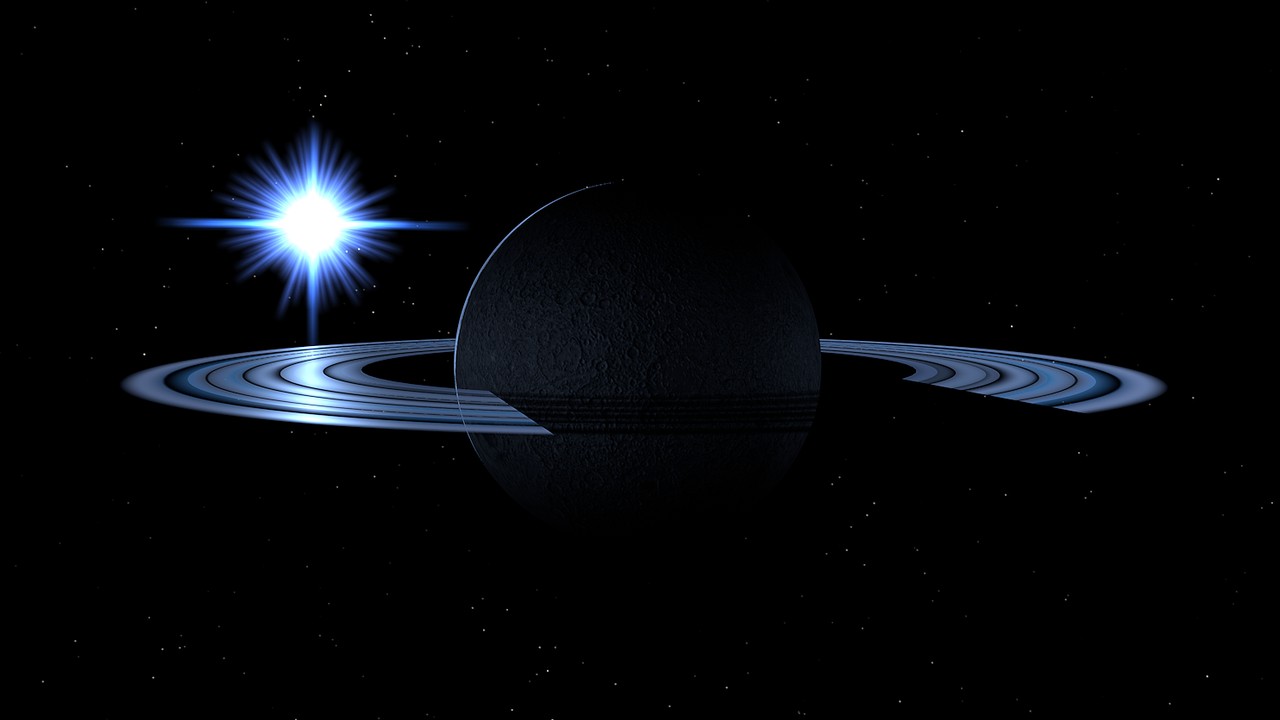
I thought it would look nice if I had a ringed planet in the scene, with the light of the distant bright blue-white star reflecting from the ice particles in the rings, and thus began working on such a scene in Cinema 4D. Within a few hours of experimenting on this, I came up with a rather nice-looking scene. The rings are just a disc primitive, with a multi-step black/white gradient in both the color and alpha channels and a high specularity for the reflections. I added subtle lights in the ring that only affect the planet surface, to give the effect of the sun illumination reflecting from the rings and illuminating the night side of the planet surface.
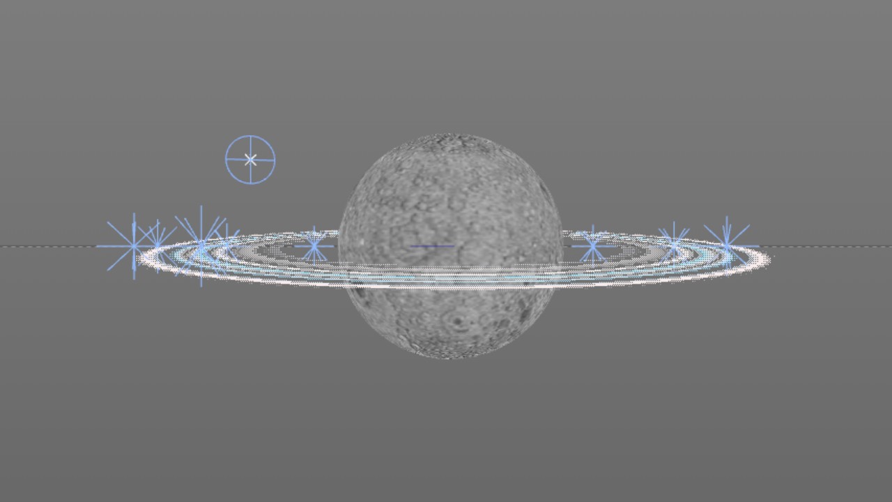
Above is a picture of the scene in Cinema4D using the same camera as I use for the skybox, and below is the actual rendering. I think this skybox could still use some additional nebulosity in the background, but I haven't yet gotten around to adding that. I don't want my skyboxes to become too busy, as I think space should be mostly black to give proper contrast between light and shadow. Many space games seem to treat space like daylight on Earth, with a lot of ambient light around. I have never liked that style.
New asteroid explosion system using a shader
I then began testing the first mission, shooting the asteroids around the star base. Running the game on my Samsung Galaxy S6 and at 1.4 render scale (meaning the render resolution is 1434x1434 instead of the default 1024x1024) I noticed some framerate drops whenever there were several asteroids concurrently exploding. I had been using the old C# -based asteroid explosion routine I originally created back in March and described in an old blog post. This code does a lot of work per frame in the C# code running on the CPU, and when it had several asteroids to handle, it obviously caused too much strain for the CPU to keep up the frame rate. So, I needed to come up with a faster way to split the asteroids.
I decided to do two major optimizations to my asteroid splitting routine:
- Pre-create an exploded asteroid mesh, so that I can simply swap the meshes when an asteroid explodes.
- Perform the asteroid fragment expansion in the shader instead of in the C# code.
After some experimenting I came up with a system where using the mesh color and uv2 arrays (plus the tangent.w value) I was able to have each exploding fragment have a section movement vector, fragment movement vector, and a value that determines when the fragment separates from the section. The resulting C# code got pretty complex, as I needed to find the adjacent triangles and determine the sections they belong to (this was the easy part, as the UV coordinate range determines this), add a new vertex and create three new triangles for each existing asteroid shell triangle, generating new normal, tangents, and the uv2 and color vectors as well. Instead of describing the C# code, it may be easier to understand this new system using the shader as an example. Here is the vertex shader, which does most of the actual work:
    float4 _ShieldSphere;  // Local position and radius of a possible ship shield sphere
    float  _CurrentPos;    // Position (0.0 .. 1.0) of the magnitude to use

    v2f vert (VertexData v)
    {
        v2f o;
        UNITY_SETUP_INSTANCE_ID(v);
        //UNITY_INITIALIZE_VERTEX_OUTPUT_STEREO(o);
        // Adjust the vertex position by the vertex movement vector
        // First calculate the movement as a whole section, using color.xyz
        // Blast radius is 100 meters from the original surface (so smaller asteroids grow bigger)
        float3 pos = v.position.xyz + (v.color.xyz * 2 - 1) * 100 * _CurrentPos;
        if (_CurrentPos - v.color.a > 0)
        {
            // Add movement of the crumbling part
            pos += float3(v.uv2.x, v.uv2.y, v.tangent.w) * (_CurrentPos - v.color.a);
        }
        o.position = UnityObjectToClipPos(pos);
        o.uv = v.uv;
        //TANGENT_SPACE_ROTATION;
        float3x3 rotation = float3x3( v.tangent.xyz, cross(v.tangent.xyz, v.normal), v.normal );
        o.lightDirection = mul(rotation, _ObjLightDir);
        o.localPos = float4(pos - _ShieldSphere.xyz, _ShieldSphere.w * _ShieldSphere.w);
        return o;
    }
First there are two uniform variables, which are set up from the C# code. _ShieldSphere determines the local position and radius of the energy shield of the closest ship. This is so that the asteroid fragments do not penetrate the ship's shields if the ship that shot this asteroid (quite possibly the player's ship) flies through the cloud of the exploded asteroid fragments. The _CurrentPos uniform variable is simply the phase of the explosion, 0 meaning the explosion is just starting and 1 is the fully exploded asteroid with all fragments as far away as they will go (and also as small as they will go, as the fragments shrink as they fly away from the center).
The actual vertex shader begins by calculating the position of the input vertex. This is based on the original vertex position v.position.xyz which is then adjusted by 100 times the current explosion phase times the segment movement vector v.color.xyz. Since the color vector range is 0..1, I multiply it by 2 and shift it down by 1, to get a range of -1 .. 1 for the movement vector. There are six movement vectors for the six separate UV sections of the asteroid, so the asteroid always splits into six major parts.
Next the v.color.a is checked against the current explosion phase, to determine if it is time for this vertex to crumble away from the main section. If it is, the vertex position is further adjusted by the vector (v.uv2.x,v.uv2.y,v.tangent.w) multiplied by the fraction of time that has passed since this vertex crumbled away from the main section. I could use v.tangent.w for this purpose after I realized that all the tangent vectors in my asteroid had v.tangent.w value of -1, which meant that instead of using the original cross(v.normal, v.tangent.xyz) * v.tangent.w formula in the TANGENT_SPACE_ROTATION calculations, I could simplify it to just cross(v.tangent.xyz, v.normal) giving the exact same result, leaving v.tanget.w free to be used as the third component of the fragment vertex movement vector. Otherwise I would have had to use something like uv3.x for this, spending additional memory and time during the draw calls.
The rest of the code just calculates the normal stuff that a vertex shader does, calculating the screen position of the vertex and the tangent-space light direction of the vertex. Finally, also the shield sphere origin position and distance (squared) is calculated and sent to the fragment shader. The fragment shader is rather simple, the only interesting bit is the check for whether the fragment is within the shield sphere, and then removing (clipping) this fragment out if it is:
    fixed4 frag (v2f i) : SV_Target
    {
        //UNITY_SETUP_STEREO_EYE_INDEX_POST_VERTEX(i);
        // Clip fragments within the closest ship shield radius
        if (dot(i.localPos.xyz, i.localPos.xyz) < i.localPos.w)
        {
            clip(-1.0);
            return 1.0;
        }
        fixed4 tex = tex2D(_MainTex, i.uv);
        fixed3 tangentSpaceNormal = tex.rgb * 2 - 1;
        fixed4 col = tex.a * (DotClamped(i.lightDirection, tangentSpaceNormal) * 3 * _LightColor0);
        return col;
    }
The resulting shaders became reasonably performant, with the vertex shader performance as follows:
  7 work registers used, 8 uniform registers used, spilling not used.

                          A       L/S     T       Bound
  Instructions Emitted:   23      19      0       A
  Shortest Path Cycles:   11.5    19      0       L/S
  Longest Path Cycles:    11.5    19      0       L/S
And the fragment shader like this:
  2 work registers used, 1 uniform registers used, spilling not used.

                          A       L/S     T       Bound
  Instructions Emitted:   6       3       1       A
  Shortest Path Cycles:   1       1       0       A, L/S
  Longest Path Cycles:    2.5     3       1       L/S
Testing this new system in Gear VR using my Samsung Galaxy S6 caused no framerate drops even with several asteroids in the explosion phase simultaneously.
The exploded asteroids have 5860 vertices and 2016 triangles, so they are rather complex meshes and having several visible at one time can still cause
slowdowns, but normally in my scenes there should not be very many exploded asteroids visible at any one time.
Story narration and voice acting
In the beginning of June I then decided to tackle the big issue where I needed help from other people: Story narration and voice acting. In my original LineWars II game I had a story (created by Raymond Bingham, who had done some work for Epic Megagames / Safari Software at the time) which was shown as a text scroller before each mission began. Such text scrollers do not work very well in virtual reality games, so I wanted to have a voice narration instead in LineWars VR. But how to find someone natively speaking English and willing to do the narration?
I had joined the freesound.org site a few years ago, when I was looking for some sounds for one of my other projects. I decided to go back to that site and see if I could find someone who would be willing to help me out. I checked some voice samples from various people, and then found the page by TheScarlettWitch89. She had a pleasant young voice, had only been a member for a little while (which meant she was probably still active on the site), and mentioned being open to requests, so I decided to send her a private message and ask whether she would be interested in giving her voice for the story narrator of my game. She responded quickly and was interested in this project, which was great! I spent a couple of days coming up with the actual story narration (I had to shorten the textual story somewhat, as I believe the players are not interested in hearing longwinded narrations) and sent her the texts. I just recently received the actual narrations from her, which do sound very nice and should fit my game perfectly. My big thanks again to TheScarlettWitch89 for generously helping me with this project!
Okay, now the story narration was handled, but I also had some textual battle chatter (and friendly fire warnings) in my original LineWars II game. These too would be nice to get converted to actual human voices. I again checked freespound.org, and found some nice fighter pilot battle chatter lines by AlienXXX and shadoWisp back from 2015. These had many usable lines, but as I would like to have the call signs like "Cobra One" included in the messages, I decided to post a forum post on the sample request forum of the freesound.org site. I also sent thanks and a query about their interest to do some voice acting specifically for my game to both AlienXXX and shadoWisp. AlienXXX responded and was willing to help me out (thanks again AlienXXX!), but I haven't heard back from shadoWisp. This is not all that surprising, as she seems to have not been active on the site since 2015.
After a few days with no replies to my forum post and encouraged by the responses I had gotten for the two private messages I had sent, I decided to start contacting people directly via private messages. I searched for people that had done something similar before, that had been active recently, and had mentioned being available for requests on their home pages. I have up to nine friendly fighters (and a few cruisers) in my missions, so I would need around ten or so different voices for the battle chatter. I can use the shadoWisp samples for one voice if necessary, but I still needed around ten other voices.
Somewhat to my surprise, most of the people I had sent private messages responded and were willing to donate their voices to my game. At the moment the following people have generously agreed to help me out, some of them have already sent me their samples. There are even some professional voice actors in the mix willing to help me out, which is pretty amazing! Thank you again to all of you!
- EFlexTheSoundDesigner (Evan Boyerman)
- AnthonyChan0 (Anthony Chan)
- drotzruhn (Alexandra Drotz Ruhn)
- 11linda (Ashley Eddy)
- ellenmentor (Ellen Mentor)
- LittleRainySeasons (Darrelle Jed Montojo)
- AlienXXX (César Rodrigues)
- womb_affliction (Katarina Rose)
Energy shield shader
Okay, now the status of the voice stuff began to look good, so I wanted to get back to programming the game. The next major feature I wanted to add was the energy shield around the ships. In my original LineWars II the ships flashed white when they got hit, but I wanted to have a proper spherical energy shield around the ships in LineWars VR. I was not exactly sure what kind of an effect I wanted, so I made a Google image search for "spaceship energy shield". One of the first hits was from a blog post called Screen Space Distortion and a Sci-fi Shield Effect by Kyle Halladay. This looked pretty neat, so I read through his blog post, and noticed that he had generously shared the source code for the effect. His effect used some screen space distortion, which I did not think was very relevant for what I was after, but the actual energy shield sphere was very useful.
His energy shield shader could handle up to 16 simultaneous hits, with 4 times 4x4 matrices handling the required input variables. I decided that four simultaneous hits are plenty enough for my uses, so I simplified the shader to only use one 4x4 matrix. His shader also used a plasma texture to animate the hit effects, I decided to go with just a simple shock wave. He had a neat Fresnel effect in his shader, which I did decide to copy for my shader as well.
Here is the actual shader code I use in my version of the shield shader. The vertex shader does nothing particularly interesting, besides sending the maximum intensity of all the four shield hits to the fragment shader in oNormal.w value. This is used to handle the shield edge Fresnel effect.
    float4x4 _Positions;    // 4 separate shield hit positions in local coordinates
    float4   _Intensities;  // 4 separate shield hit intensity values
    float4   _Radius;       // 4 separate shield hit shock wave radiuses
    half4    _ShieldColor;  // Color = health of the shield (blue, yellow, red)

    v2f vert (appdata v)
    {
        v2f o;
        o.vertex = UnityObjectToClipPos(v.vertex);
        o.oPos = v.vertex.xyz;
		// Put the biggest hit intensity into oNormal.w
        o.oNormal = float4(v.normal, max(_Intensities.x,max(_Intensities.y,max(_Intensities.z,_Intensities.w))));
        o.oViewDir = normalize(_ObjectCameraPos - v.vertex.xyz);
        return o;
    }

    // This subroutine calculates the intensity of the fragment using all the hit positions.
    float calcIntensity(float3 oPos)
    {
        float3 impact0 = (_Positions[0].xyz - oPos);
        float3 impact1 = (_Positions[1].xyz - oPos);
        float3 impact2 = (_Positions[2].xyz - oPos);
        float3 impact3 = (_Positions[3].xyz - oPos);

        float4 sqrLens = float4(dot(impact0,impact0),	// Values between 0*0 and 2*2 = 0..4
                                dot(impact1,impact1),
                                dot(impact2,impact2),
                                dot(impact3,impact3));

        float4 cmpRad = sqrLens < _Radius ? cos(5 * (sqrLens - _Radius)) : 0;
        float4 add = cmpRad * _Intensities;
        return add.x + add.y + add.z + add.w;
    }

    fixed4 frag (v2f i) : SV_Target
    {
        float ang = 1 - (abs(dot(i.oViewDir, i.oNormal.xyz))); // Fresnel effect, shield edges show up brighter than the center
        return (ang * i.oNormal.w + calcIntensity(i.oPos)) * _ShieldColor;
    }
The interesting stuff happens in the calcIntensity subroutine. It first separates the four hit positions from the 4x4 uniform matrix
_Positions and calculates the impact positions relative to the current fragment. Then it prepares the sqrLens vector, which
contains the four squared distances of these impact positions. Next a vector cmpRad is calculated, this in turn contains the fragment
intensity relative to the squared distance. I am using a cos trigonometric function to calculate this, so that the blast front (or
shock wave) has the largest intensity (as cos(0) = 1, where _Radius == sqrLens), and the shock wave then follows a cosine
function when the distance to the hit origin is less than _Radius, and zero if the distance is greater. The multiplier 5 is just
a value I experimentally determined to make the shield hit look nice.
Then the cmpRad is multiplied by the _Intensities vector, as each of the four hits have their own intensity decay value. These four intensities are then added up, to get the final fragment intensity value. In the fragment shader first the fresnel effect is calculated (using the shield hemisphere normal vector and a vector towards the camera), and then this Fresnel effect is multiplied with the maximum intensity of the currently active shield hits, and then the summed-up intensity of the hit shock waves is added, and finally the color of the shield is used to make the shield show the ship's shield health (blue = healthy, yellow = half health, red = about to collapse).
Of course, I was interested to see what the Mali Offline Compiler thinks the performance of these shaders is, so I ran them through the compiler and got the following results. Not too bad, considering the shield can handle four separate hits, and the fact that the shields are not visible all the time.
  8 work registers used, 8 uniform registers used, spilling not used.

                          A       L/S     T       Bound
  Instructions Emitted:   17      15      0       A
  Shortest Path Cycles:   10.5    15      0       L/S
  Longest Path Cycles:    10.5    15      0       L/S
  4 work registers used, 6 uniform registers used, spilling not used.

                          A       L/S     T       Bound
  Instructions Emitted:   15      3       0       A
  Shortest Path Cycles:   7       3       0       A
  Longest Path Cycles:    7       3       0       A
To make the effect work obviously needs some C# code to actually send those uniform values to the shader. This is handled by a couple of routines, first a static ShieldHit routine, which just checks the current _intensity vector values, and chooses the slot which has the lowest intensity (is the oldest hit). Then it sets up the new uniform values like this:
    script.matrix.SetRow(slot, localHitPos);
    script.intensity[slot] = 1f;
    script.radius[slot] = 0f;
    mat.SetMatrix("_Positions", script.matrix);
That is, the new local shield hit position is set to the correct row in the matrix, and the intensity of that slot is set to one,
and the radius to zero. The position matrix is sent to the shader in this routine, as it does not change every frame. Then in the
Update routine of the actual shield object I handle the radius increase and the intensity decrease, using a frameCount
variable, whose initial value is 90 at the moment (so the shield flash lasts 1.5 seconds). First, I check if all the intensities are
zero, in which case I can hide the whole shield.
    void Update () {
        if (intensity == Vector4.zero)
            gameObject.SetActive(false);
        else
        {
            intensity = new Vector4(Mathf.Clamp(intensity.x - 1f / frameCount, 0f, 1f),
                                    Mathf.Clamp(intensity.y - 1f / frameCount, 0f, 1f),
                                    Mathf.Clamp(intensity.z - 1f / frameCount, 0f, 1f),
                                    Mathf.Clamp(intensity.w - 1f / frameCount, 0f, 1f));
            radius = new Vector4(radius.x + 1f / frameCount, radius.y + 1f / frameCount, radius.z + 1f / frameCount, radius.w + 1f / frameCount);
            m_Material.SetVector("_Intensities", intensity);
            m_Material.SetVector("_Radius", radius);
        }
    }
Here below is a quick animated GIF showing a single laser blast hitting the rear shield of a ship. The Fresnel effect shows the hemisphere shape of the shield, while the hit itself generates a slowly dissipating shock wave.
That's about as far as I have gotten during the last month or so. I am currently working on the texturing of the Cobra and Pirate ships (the current Cobra texture can be seen in the above GIF. It has some nice features already, but it could use some more work). I am keeping all the Cobra and Pirate ships very low-poly (the absolute top limit is 300 vertices, as I want to take advantage of Unity's dynamic batching with these), so I can't make them very complex shape-wise. I do use normal mapping in the textures, so I can add features using surface normals, though.
Thank you for your interest in LineWars VR!
May 20th, 2018 - Progress Report
Cobra Cockpit shadows switched from Cube Map to procedural shadows
By the end of the last blog post I had figured out a way to combine my cockpit texture shadow maps to a single Cube Map. However, just the next day, when trying to improve the Cobra cockpit shadow maps, I realized that the Cube Map just isn't very suitable for my non-rectangular cockpit shape. I decided to check whether I could use procedural shadow planes instead of a Cube Map to handle the sun shining through cockpit windows. I had already implemented something similar for the cruiser shadows, but this time I would need a rather complex window shape, which was not even aligned with any coordinate axis.
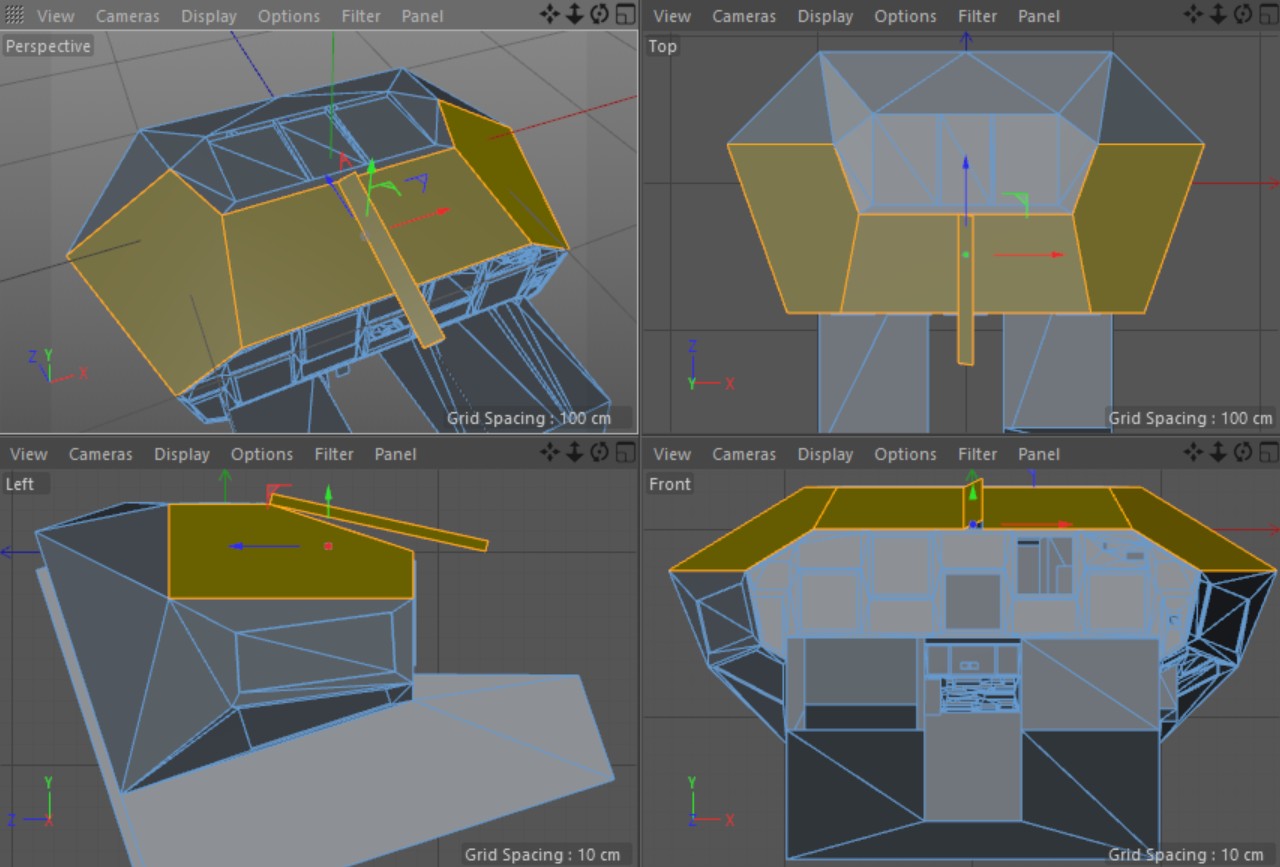
I spent some time thinking about the problem, and did some experiments, and noticed that the Cobra cockpit windows could actually be handled by three planes whose borders would align with the object coordinates, if I would pitch the whole cockpit object 18 degrees up. This would make the instrument panel vertical, and the side window bottom edges nearly horizontal. Since only the instrument panel edges were located where I did not want to move them, I could move the other window borders freely to make the side window top and bottom edges exactly horizontal, and also make the rear edges of the windows vertical. This would make it possible to check for the fragment being in shadow or light with simple checks for intersection point Y or Z coordinate being over or below a given limit. In the image below is the CobraCockpit mesh in Cinema4D, with the windows (and the center bar of the front window) shown as yellow polygons. The Left view shows nicely how I was able to have the side windows aligned to the local coordinate system, even though in the Perspective view they look not to be aligned on any axis.
Next, I just needed a suitable algorithm for a ray-plane intersection. I had used only coordinate-aligned planes before this, so I was not sure how much more difficult handling such an arbitrarily-oriented plane would be. Luckily, it turned out that an algebraic method for Ray-Plane Intersection is pretty simple. I just need to calculate the t term for the plane, after which the ray-plane intersection for a ray starting at point P and going towards vector V is simply P + tV. This term t of the plane is based on the plane normal and the vector V, both of which will stay constant throughout the frame, and the point itself. The algorithm for calculating t is -(P.N + d)/(V.N). The value d is constant for the plane (it is -P.N for any point P on the plane) and can be precalculated. I found a nice Vector Dot Product Calculator on the net, which allowed me to just input the coordinates from my Cinema 4D cockpit object and get the d term for my shadow planes as output.
So, now it was a matter of implementing the code into my Cobra cockpit shader, and into my C# code that previously calculated the needed sun ray parameters for the Cube Map algorithm. I decided to use four shadow planes: Front window, left side window, right side window, and the window strut in the middle of the front window. I originally had the center bar/strut horizontal, but after some tests I realized that I could get nicer shadows if I were to use two slightly slanted shadow planes, depending on which side of the cockpit the sun shines from. So, in my C# code I had the plane normals set up in the Start method:
    m_N1 = new Vector3(0, -0.95f, -0.3125f);              // Front Plane normal
    m_N2 = new Vector3(-0.51307f, -0.83868f, -0.18270f);  // Left Plane normal
    m_N3 = new Vector3(0.51307f, -0.83868f, -0.18270f);   // Right Plane normal
    m_N4m = new Vector3(-0.44702f, -0.87392f, -0.19088f); // Center bar normal
    m_N4p = new Vector3(0.44702f, -0.87392f, -0.19088f);  // Center bar normal
In the Update method I then needed to pass the current light direction (in object coordinate system), along with the denominators for the plane t terms (meaning the result of V.N for each of the shadow planes). I have a uniform float4 variable _ShadowPlaneMultipliers in my shader, and pass these denominators inverted so I can just multiply instead of divide them in the shader. I'm not sure if converting divisions to multiply operations in the shader makes the shader run any faster, but at least it should not be any slower. Thus, this is what the Update part of my C# code does per each frame (the Movement.SunDirection stores the static sun direction of the scene in world coordinates):
    Vector3 lightDir = Vector3.Normalize(transform.InverseTransformDirection(Movement.SunDirection));
    m_Material.SetVector("_ShadowsLightDir", lightDir);
    // Setup the shadow plane inverse multipliers
    float d1 = Vector3.Dot(lightDir, m_N1);
    float d2 = Vector3.Dot(lightDir, m_N2);
    float d3 = Vector3.Dot(lightDir, m_N3);
    Vector4 mult = new Vector4(1f / d1,  1f / d2,  1f / d3, 1f / Vector3.Dot(lightDir, lightDir.x < 0 ? m_N4p : m_N4m));
    m_Material.SetVector("_ShadowPlaneMultipliers", mult);
Now then, what do the shaders look like? If we take the vertex shader first, that is responsible for calculating the ray-plane intersections with all the four planes. The ray is starting from the vertex position in object local coordinates (v.vertex.xyz) and going towards the light direction (also in object local coordinates) _ShadowsLightDir. The calculations need again the plane normals, the constant d terms of the ray-plane intersection equations, and the denominators which we get from the uniform _ShadowPlaneMultipliers sent by the C# code. I could have used uniforms to store the data like the normal vectors, but I noticed using the Mali Offline Compiler that giving the values "inline" within the code is faster. The compiler is smart enough to only use the dimensions of the vectors that I actually need (for example, it does not calculate the y component of the P1 vector at all, because I don't use it in the shadowData1 or shadowData2 output interpolators, and for the P4 it only calculates the x component).
    // ----- Shadow plane calculations -----
    half3 N1 = half3(0,-0.95,-0.3125);              // Front Plane normal
    half3 N2 = half3(-0.51307, -0.83868, -0.18270); // Left Plane normal
    half3 N3 = half3(0.51307, -0.83868, -0.18270);  // Right Plane normal
    half3 N4 = half3(_ShadowsLightDir.x < 0 ? 0.44702 : -0.44702, -0.87392, -0.19088); // Center bar normal
    float t1 = -(dot(v.vertex.xyz, N1) + 0.4302) * _ShadowPlaneMultipliers.x;
    float t2 = -(dot(v.vertex.xyz, N2) + 0.8023) * _ShadowPlaneMultipliers.y;
    float t3 = -(dot(v.vertex.xyz, N3) + 0.8023) * _ShadowPlaneMultipliers.z;
    float t4 = -abs(dot(v.vertex.xyz, N4) + 0.4689) * _ShadowPlaneMultipliers.w; // Handle vertices on the "wrong" side of the plane using abs()
    half3 P1 = v.vertex.xyz + t1 * _ShadowsLightDir;
    half3 P2 = v.vertex.xyz + t2 * _ShadowsLightDir;
    half3 P3 = v.vertex.xyz + t3 * _ShadowsLightDir;
    half3 P4 = v.vertex.xyz + t4 * _ShadowsLightDir;
    o.shadowData1 = half4(t1 < 0 ? 100 : P1.x, t2 < 0 ? 100 : P2.y, t1 < 0 ? 100 : P1.z, t2 < 0 ? 100 : P2.z);
    o.shadowData2 = half3(t4 < 0 ? 100 : P4.x, t3 < 0 ? 100 : P3.y, t3 < 0 ? 100 : P3.z);
If the t term of the equation is negative, it means the sun is shining from the same side of the plane as where the vertex is. This means the vertex will be in shadow, and thus I give a large value of 100 to the output interpolator in this situation. This works fine for polygons whose vertices are always on the same side of the plane. However, the slanted center bar has some polygons with vertices on opposite sides of the plane, so I needed to use the absolute value of the dot product to mirror the vertices to the same side of the plane. If I didn't do that, a polygon may have one vertex with the interpolator value of 100 and another vertex with some negative value, which would cause an invalid shadow strip to appear within the polygon. To make sure there are no cockpit vertices that are located in the actual shadow plane, I adjusted the d terms (0.4302, 0.8023 and 0.4689) slightly from their actual values, to put the shadow plane slightly outside of the window holes in the mesh.
Then, in the fragment shader, it is rather easy to check whether the interpolated ray-plane intersection position is within the window area. As I had rotated my cockpit so that all the windows had their edges axis-aligned, I could just check whether the interpolated intersection location falls within the window coordinates. For example, the center bar is 10 cm wide and located in the middle of the cockpit, so I can simply check if the x coordinate of the corresponding interpolator (P4.x in the vertex shader, sent in shadowData2.x to the fragment shader) value falls within -0.05 and 0.05. If it does, this fragment is in a shadow caused by the center bar, so I can return the shadow color value from the fragment shader. The instrument panel is located at z coordinate 14.581 cm (or 0.14581 meters) and is used as one edge for both the front window and the side windows. The intersection between the side windows and the front window is somewhat irrelevant, as the fragment gets sunlight whether the sun shines from the front window or the side window. Thus, I just used a width of -0.85 to 0.85 meters for the front window, even though this width overlaps the side windows somewhat.
    // Handle light shining in from windows
    if (i.shadowData2.x > -0.05 && i.shadowData2.x < 0.05) // Center bar shadow
        return shadowColor;
    if (i.shadowData1.x > -0.85 && i.shadowData1.x < 0.85 && i.shadowData1.z > -0.51307 && i.shadowData1.z < 0.14581)
        return lightColor;
    if (i.shadowData1.y > 0.1838 && i.shadowData1.y < 0.62579 && i.shadowData1.w > -1 && i.shadowData1.w < 0.14581)
        return lightColor;
    if (i.shadowdata2.y > 0.1838 && i.shadowdata2.y < 0.62579 && i.shadowData2.z > -1 && i.shadowData2.z < 0.14581)
        return lightColor;
    // We are in shadow
    return shadowColor;
So, the interesting question now is, how did the performance of the shaders change after this change from the (not properly working) Cube Map shadows to this procedural shadow system? Let's use the Mali Offline Compiler and check what it says. The original vertex shader took 10 arithmetic cycles and 22 load/store cycles, so the performance is bound by the load/store operations:
  7 work registers used, 7 uniform registers used, spilling not used.

                          A       L/S     T       Bound
  Instructions Emitted:   20      22      0       L/S
  Shortest Path Cycles:   10      22      0       L/S
  Longest Path Cycles:    10      22      0       L/S
After adding all the code to handle the shadow planes, the arithmetic instructions nearly doubled! However, since the shader
is bound by the load/store performance (which only increased by two cycles), the actual performance degradation is not
very significant.
  8 work registers used, 8 uniform registers used, spilling not used.

                          A       L/S     T       Bound
  Instructions Emitted:   35      24      0       A
  Shortest Path Cycles:   17.5    24      0       L/S
  Longest Path Cycles:    17.5    24      0       L/S
The original fragment shader (using the Cube Map shadow system) had this kind of performance:
  3 work registers used, 3 uniform registers used, spilling not used.

                          A       L/S     T       Bound
  Instructions Emitted:   23      5       2       A
  Shortest Path Cycles:   3       2       1       A
  Longest Path Cycles:    9       5       2       A
The longest path had 9 arithmetic operations, 5 load/store operations and two texture lookups. After switching to
the procedural shadow planes, the performance characteristics changed to the following:
  4 work registers used, 1 uniform registers used, spilling not used.

                          A       L/S     T       Bound
  Instructions Emitted:   23      5       1       A
  Shortest Path Cycles:   3       4       1       L/S
  Longest Path Cycles:    7       5       1       A
The instruction counts actually remained the same, but the arithmetic cycles decreased by two, and I got rid of one
of the texture lookups (the Cube Map itself). This was very nice, I was able to fix the shadows to be correct, and
make the code run faster at the same time!
Instruments combined to a single mesh
Next, I continued my work on the Cruiser Bridge model. Pretty soon I realized that it would make more sense to have a common code for the cockpit instruments of all the three flyable ship types. Currently the Cobra cockpit instruments were partly embedded into the Cobra cockpit mesh, and partly in a separate object. Both of these had their own code to handle the instrument updating. So, I started moving the all the instruments into the separate object for the Cobra cockpit and created a new instruments object for the Cruiser bridge. These objects would work kind of like skins for the instruments, so each cockpit has their own skin, but the underlying C# code would be the same. After a day of working on this I had the system up and running for both the Cobra and the Cruiser cockpits.
Cruiser Bridge shadows switched from Cube Map to procedural
After I got the Cobra cockpit shadows improved using procedural shadows instead of the Cube Map system, I wanted to make the same change also to the Cruiser bridge object. However, the problem here was that the cruiser bridge actually has 19 separate rectangular windows! The front and ceiling windows are actually nicely oriented along the coordinate axis, so those would be easy to handle using the Cube Map. Only the slanted side windows were a problem with the Cube Map system. At first, I tried to create a sort of a hybrid system, where the front and ceiling windows were handled by the Cube Map, and the side windows procedurally, but it soon became evident that this hybrid system would just enhance the worst aspects of both of those systems. Since the Cube Map could not handle all the windows, I had to switch completely to the procedural system.
I used much the same system as with the Cobra cockpit shadow planes, except that the front and ceiling shadow planes were somewhat simpler, as they are axis-aligned. Thus, the vertex shader for the Cruiser bridge turned out slightly simpler. Here shadowData1 contains the interpolators for the front and ceiling windows, and shadowData2 the interpolators for the left and right windows.
    // Shadow planes
    float2 dist = (v.vertex.yz - float2(1.601, 7.101)) / _ShadowsLightDir.yz;	// Y and Z plane distances
    float4 ip = v.vertex.xzxy - _ShadowsLightDir.xzxy * dist.xxyy;
    o.shadowData1 = float4(dist.x > 0 ? 100 : ip.x, ip.y, dist.y > 0 ? 100 : ip.z, ip.w);
    half3 Nr = half3(-0.86824, 0, -0.49614);
    float tr = -(dot(v.vertex.xyz, Nr) + 6.1778) / dot(_ShadowsLightDir, Nr);
    half3 Pr = v.vertex.xyz + tr * _ShadowsLightDir;
    half3 Nl = half3(0.86824, 0, -0.49614);
    float tl = -(dot(v.vertex.xyz, Nl) + 6.1778) / dot(_ShadowsLightDir, Nl);
    half3 Pl = v.vertex.xyz + tl * _ShadowsLightDir;
    o.shadowData2 = float4(tl < 0 ? 100 : Pl.z, Pl.y, tr < 0 ? 100 : Pr.z, Pr.y);
The fragment shader however became pretty complex, as there are so many separate windows. I tried to order the if clauses in a way that the total number of clauses for the longest path would stay as low as possible. The main if clauses check the overall window areas, and the sub-clauses then exclude the window struts within these areas.
    if (i.shadowData1.x > -2.94 && i.shadowData1.x < 2.94 && i.shadowData1.y > 2.56 && i.shadowData1.y < 6.94)
    {
        // Sun shines through the ceiling windows.
        if (i.shadowData1.y < 3.94 && i.shadowData1.x < 1.44 && i.shadowData1.x > -1.44)
            return sunColor;
        if (i.shadowData1.y < 4.06 || (i.shadowData1.y > 5.44 && i.shadowData1.y < 5.56))
            return shadowColor;
        if ((i.shadowData1.x > 1.44 && i.shadowData1.x < 1.56) || (i.shadowData1.x > -1.56 && i.shadowData1.x < -1.44))
            return shadowColor;
        return sunColor;
    }
    if (i.shadowData1.z > -2.94 && i.shadowData1.z < 2.94 && i.shadowData1.w > -1.44 && i.shadowData1.w < 1.44)
    {
        // Sun shines through the front windows.
        half fX = abs(i.shadowData1.z);
        if (abs(i.shadowData1.w) < 0.06 || ( fX > 1.44 && fX < 1.56))
            return shadowColor;
        return sunColor;
    }
    if (i.shadowData2.x > 2.60171 && i.shadowData2.x < 6.99752 && i.shadowData2.y > 0.06 && i.shadowData2.y < 1.44)
    {
        // Sun shines through the left windows.
        if ((i.shadowData2.x > 5.49752 && i.shadowData2.x < 5.60171) || (i.shadowData2.x > 3.99752 && i.shadowData2.x < 4.10171))
            return shadowColor;
        return sunColor;
    }
    if (i.shadowData2.z > 2.60171 && i.shadowData2.z < 6.99752 && i.shadowData2.w > 0.06 && i.shadowData2.w < 1.44)
    {
        // Sun shines through the right windows.
        if ((i.shadowData2.z > 5.49752 && i.shadowData2.z < 5.60171) || (i.shadowData2.z > 3.99752 && i.shadowData2.z < 4.10171))
            return shadowColor;
        return sunColor;
    }
    return shadowColor;
The resulting performance by the Mali Offline Compiler turned out to be as follows, first the vertex shader:
  8 work registers used, 8 uniform registers used, spilling not used.

                          A       L/S     T       Bound
  Instructions Emitted:   32      23      0       A
  Shortest Path Cycles:   17.5    23      0       L/S
  Longest Path Cycles:    17.5    23      0       L/S
And then the fragment shader:
  4 work registers used, 1 uniform registers used, spilling not used.

                          A       L/S     T       Bound
  Instructions Emitted:   52      6       1       A
  Shortest Path Cycles:   1       1       1       A, L/S, T
  Longest Path Cycles:    8.5     6       1       A
The vertex shader performance is pretty similar to that of the Cobra cockpit vertex shader, but the fragment shader is
somewhat slower due to all those if clauses. Even this performance is still slightly better than what the performance
was using the Cube Map, so I was pretty happy with the end result.
Cobra cockpit Android texture problem
After I had changed both of these shadow systems, and everything worked fine within the Unity editor, I finally tested the result on the actual Gear VR hardware using my Android phone. The Cruiser bridge worked fine, but the Cobra cockpit had a strange issue where some of the cockpit panels were either black or white depending on the orientation, and not using either of the shadowColor or lightColor as they should have! I again had no idea what could cause this, but as I had already encountered something similar before, I at least had some ideas as to how to debug the problem.
I began debugging this problem by changing the order of the interpolators in the structure and got various other weird effects with the textures. With a certain order of the interpolators, the textures were "swimming", with another order I got the black and white problem, but I could not find an order that would be without issues. After some more experimenting I finally noticed, that if I made all the interpolators have the same number of dimensions, the problem vanished. Originally, I had declared my data structure like this:
struct v2f
{
    float4 vertex : SV_POSITION;
    float2 uv : TEXCOORD0;
    float3 normal: TEXCOORD1;
    float4 channel: TEXCOORD2;
    float3 cameraDir: TEXCOORD3;
    float4 shadowData1: TEXCOORD4;
    float3 shadowData2: TEXCOORD5;
}
When I then remapped all the shadowData2 interpolators into the extra dimensions of the other structure members, I got rid of the weird texture problem. All the interpolators now have the same 4 dimensions, and the structure looks like this (with uv.z, uv.w and normal.w containing the old shadowData2 interpolators):
struct v2f
{
    float4 vertex : SV_POSITION;
    float4 uv : TEXCOORD0;
    float4 normal: TEXCOORD1;
    float4 channel: TEXCOORD2;
    float4 cameraDir: TEXCOORD3;
    float4 shadowData1: TEXCOORD4;
}
Pilot avatar and Cruiser bridge modeling and texturing
Now that I had the shadows working properly, it was time to continue modeling the Cruiser bridge, and at the same time the pilot avatar. There was quite a bit of work involved in both the modeling and texturing, so even after working on this for a couple of weeks, it is still far from finished. Again, texturing is the most time-consuming part of the process.
When working for the instrumentation of the Cruiser bridge, I decided that the captain should have MFD display panels at the ends of the arm rests. These will contain the ship status and damage displays on the left panel, and the communications stuff on the right panel. These would correspond to the leftmost and the third display panel in the Cobra cockpit. The Cobra cockpit has the 3D radar display showing on the second display panel but I decided to have a large holo projector instead in the Cruiser bridge. This holo projector will be on the floor level in front of the captain, while the captain's chair is on an elevated level with unrestricted views through the windows.
Below and in front of the captain are the stations for weapons and communications officers (or some such), which should also contain some human characters sitting on the stations. Both of those stations are still only at a placeholder level, no actual work has been done either properly modeling or texturing the stations.
Vertex color as light intensity
While working on the preliminary texturing of the Cruiser bridge model, I realized that in several locations I would like to have some additional lights shining on the surface. The Cruiser bridge (same as the Cobra cockpit) should be rather dark when the sun is not shining through the windows, but there should still be some modest lighting. As I am trying to fit all the textures into a rather limited texture atlas, I could not bake all the lighting into the textures either. How to solve this issue?
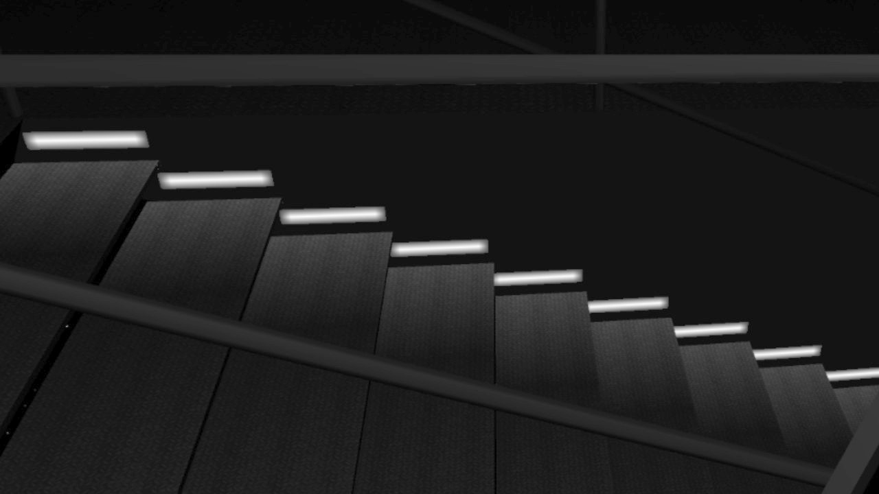
I remembered reading from Unity documentation that if a mesh does not have Vertex Color information, Unity will automatically generate an array of full white Vertex colors. I thought that rather than wasting memory with this default array, I could actually use the Vertex Colors for something useful, and store information about how much light each vertex of the object is receiving. Then it was just a matter of writing a C# code that would calculate the received light from whatever light emitters I decided to have in my objects. Here is an example image of a stairwell in the Cruiser bridge, where a light in a wall is illuminating each step.
Pilot avatar arm movements
After some time working on the bridge and the pilot avatar, I decided it was time to tackle the difficult issue, making the pilot arms move. I wanted to have the left throttle hand follow the actual throttle control input, and similarly the right hand to follow the joystick input. I thought about having the pilot's legs move on the pedals for the yaw input (similarly to how airplane controls work), but decided to have yaw control also move the joystick hand, to keep the number of moving objects as low as possible.
I started with the throttle hand, and simply made it rotate around it's pivot point which was inside the arm rest. The rotation worked, but I noticed that the procedural shadows were not correct. I realized that simply moving the object will not work, as I used the same procedural shadows for the throttle hand object as I used for the bridge object. The procedural shadows use hardcoded distances from the object origin to the shadow planes, so the object origin can not move or rotate, or the shadows will be incorrect. But I want to move and rotate the pilot's arms! How can I solve this problem?
I thought about having separate dynamic procedural shadow values in the throttle and joystick arm shaders, but it soon became evident that this would make the shader much more complex and slower. So, the remaining option was to keep the object stationary, and instead move the vertices of the object. I wrote a quick test that used some C# code to rotate the vertices of the throttle hand object. This worked, after I moved the throttle hand to the bridge coordinate system origin, and then also remembered to adjust the bounding box of the object, otherwise the object would not be visible when it should!
However, moving all the vertices in the C# code for every frame did not seem like a good solution, as the joystick object has 1233 vertices in Unity, and even the simpler throttle hand has 362 vertices. I would also need to move the lower and upper arms, so it felt like moving approximately two thousand vertices in C# code for each frame would be an unnecessary burden for the CPU. How about moving the vertices using the GPU?
Since the vertex shader needs to transform the vertices from the object coordinate system to world coordinates and then to screen coordinates anyways, I thought that perhaps adding one more transformation to this operation would be the best way to solve this issue. After all, performing such transformations is what the GPU is meant for. However, this meant I needed to delve into those scary rotation matrices, which I feel I do not fully understand. Luckily, it turned out that Unity has simplified the rotation matrix generation, so that I could generate the required matrix simply using the Matrix4x4.TRS method. This gets a translation vector, rotation quaternion, and a scale vector as parameters, and returns a matrix that can directly be used in the shader. Thus, I just needed to add a float4x4 uniform variable to my vertex shader, and multiply both the object vertex and normal by this matrix inside the vertex shader:
float4x4 _JoystickProjMat;
    float3 vertex = mul(_JoystickProjMat, v.vertex);  // Translate and rotate the joystick/throttle/arm
    float3 normal = mul(_JoystickProjMat, v.normal);  // Only xyz input, so translation is not applied
This change caused the vertex shader to spend 3 additional arithmetic GPU cycles, compared to the original Cruiser Bridge vertex shader.
Since the vertex shader is still load/store -bound, this should not actually affect the performance all that much. The fragment shader
needed no changes because of this system.
  8 work registers used, 12 uniform registers used, spilling not used.

                          A       L/S     T       Bound
  Instructions Emitted:   35      23      0       A
  Shortest Path Cycles:   19.5    23      0       L/S
  Longest Path Cycles:    19.5    23      0       L/S
What remained was the generation of the matrix, which I did in the Update method of a C# code that is attached to the throttle
hand object. I rotate the throttle hand object up to plus or minus 15 degrees around the X axis, based on the throttle range between
zero and MaxSpeed:
    Vector3 trans = new Vector3(-0.44f, -0.12f, 2.0f);  // Translate the object to where we want it
    Quaternion rot = Quaternion.Euler(myData.CurSpeed * 30f / myData.MaxSpeed - 15f, 0, 0); // Throttle hand rotation, only around X axis
    m_Mat.SetMatrix("_JoystickProjMat", Matrix4x4.TRS(trans, rot, new Vector3(1, 1, 1)));
After I got the throttle hand working, it was time to attach the lower arm to it. This was something I had been partly looking forward to and partly dreading, as I would need to invent some way to attach some vertices of one object to another. I needed to have the wrist vertices of the lower arm stay stationary relative to the wrist vertices of the throttle hand, even though the lower arm should move separately to the hand. I looked into Unity skinned mesh system, but it felt rather overkill, as I only needed to move a few vertices of the lower arm object. In the end I decided to move these few vertices using the C# code. But this again forced me to look into the required rotation matrices.
Since I use rotation matrices in the vertex shader to rotate the object vertices, and now I needed to keep some vertices from rotating (or rather, have them rotate differently), it seemed like similar rotation matrices would be the solution here as well. However, since I needed to combine two different rotations into one, I thought that trying to build the rotation matrix from these two quaternions might be less efficient than just using those two quaternions directly. I decided to attempt to solve the problem using just quaternions. Here is first the code that handles the left lower arm vertex movement, followed by some explanations regarding the code.
    //------------
    // Adjust the vertex positions by the current throttle amount
    //------------
    Quaternion handRot = Quaternion.Euler(myData.CurSpeed * 30f / myData.MaxSpeed - 15f, 0, 0);  // Throttle hand rotation, only around X axis
    Quaternion armRot = Quaternion.Euler((myData.MaxSpeed * 3f / 4f - myData.CurSpeed) * 8f / myData.MaxSpeed, 0, 0);  // Arm rotation
    Quaternion armInv = Quaternion.Inverse(armRot);
    // First calculate how much the whole lower arm should move.
    // It moves as much as the wrist moves because of the throttle rotation,
    // minus how much the arm rotates because of the elbow joint connection.
    Vector3 llArmWristPos = new Vector3(-0.00325f, 0.19955f, -0.11151f);  // Wrist position of avatar LeftLowerArm
    Vector3 wristPos = (handRot * llArmWristPos) /*- llArmWristPos*/ - (armRot * llArmWristPos) /*+ llArmWristPos */;
    Vector3 trans = new Vector3(-0.44f, -0.12f, 2.0f) + wristPos;
    // Translate to the opposite direction and rotate the wrist connected vertices
    for (int i = 0; i < m_VertexData.Count; i++)
    {
        Vector3 v = m_VertexData[i].vertex;
        m_Verts[m_VertexData[i].idx] = handRot * v      // Rotate the wrist vertices by the throttle hand rotation
                                     + armInv * v - v   // Remove the effect of the _JoystickProjMat rotation
                                     - wristPos;        // Remove the effect of the _JoystickProjMat wrist-relative translation
    }
    m_Mesh.vertices = m_Verts;
    // Lower arm rotation
    m_Mat.SetMatrix("_JoystickProjMat", Matrix4x4.TRS(trans, armRot, new Vector3(1, 1, 1)));
First, I generated the same handRot quaternion as with the throttle hand, but I then also added a small rotation of the lower arm
using the armRot quaternion. This makes the arm move slightly more naturally. For the wrist vertices I need to remove this arm
rotation, so I generated an inverted rotation armInv from the armRot as well. After that, I calculate how the wrist should move.
The "wrist" in this case is part of the lower arm, so its position is based on the rotation of the llArmWristPos around the
origin (the lower arm and the throttle hand share the same origin position), plus the inverted rotation of the arm. However, instead
of using the armInv quaternion to rotate the arm, I use the original armRot negated. This way I can avoid adding the
llArmWristPos to the formula, as it gets both added and subtracted within the formula. This is probably not quite a correct way
to do this, but with a rotation only around a single axis I can get away with it. The resulting translation is then the position where
we want the lower arm, plus the wrist position.
I then go through the wrist vertices, which I had stored in the Start method into an m_VertexData array containing the vertex index in the stored m_Verts array and the original vertex position. The new vertex position for these wrist vertices is based on only the hand rotation, but since the rotation matrix in the shader rotates and translates also these vertices by the armRot and wristPos values, I need to remove the effect of both of these from the resulting vertex position. Then I just update the vertices of the mesh and send the _joystickProjMat matrix to the shader.
There is similar code for the upper arm, and for the joystick hand and right lower and upper arms. The differences between these codes are the positions, the way the lower arm moves, and the fact that the upper arm has two sets of specially moving vertices, one set at the elbow and one at the shoulder. Luckily the upper arms are the lowest-poly objects, so updating their vertices every frame should not be especially time-consuming operation. Here are the current vertex and polygon counts of the pilot avatar arm objects, as counted by Unity:
- JoystickHand: 1233 vertices, 1685 triangles, no vertices moved from the C# code.
- ThrottleHand: 362 vertices, 482 triangles, no vertices moved from the C# code.
- RightLowerArm: 144 vertices, 242 triangles, 12 wrist vertices moved from the C# code.
- LeftLowerArm: 137 vertices, 226 triangles, 14 wrist vertices moved from the C# code.
- RightUpperArm: 99 vertices, 138 triangles, 5 shoulder vertices and 11 elbow vertices moved from the C# code.
- LeftUpperArm: 92 vertices, 120 triangles, 5 shoulder vertices and 10 elbow vertices moved from the C# code.
Finally, here below is a short YouTube video demonstrating the pilot avatar arm movements, and also showing the procedural shadows on the Cruiser bridge. Note that everything is still very much work in progress. Thanks for your interest in my LineWars VR project!
Apr 21st, 2018 - Progress on Multiple Fronts
For the past month I have been working on various core technologies (and some models) I will need for my finished game. I have mainly focused on making sure the ideas I had in mind are working, and I've been jumping to the next new thing after I have confirmed the idea works. Thus, I have practically not finished anything, I have just started a lot of new development fronts. This also means I don't have a new demo video this time, as none of the new techniques are quite in the presentable form yet.
Space Station Laser Hit Damage Textures
As I mentioned at the end of my previous blog post, I continued my work on the Space Station textures by implementing some damaged textures. My idea is to switch the texture coordinates of a body panel when it gets hit, so after the first hit the panel shows a black scorch mark from the laser, the next hit to the same panel creates more damage, until the whole panel gets blown of and the underlying structure gets exposed. This is why I created my original Space Station model so, that it has many rectangular areas, which I can then replace the texture UV coordinates of. However, the main body of the station is so big that I needed to have each rectangular area consist of four body panels, and thus, I needed to have that texture having all combinations of anything between zero and four of the armor panels damaged. This ended up taking so much of my texture atlas area, that I decided to limit the damage stages to only three: Non-damaged, Once Hit, and Structure Visible. Here below is an example of those three body panels:

The code that handles the laser hitting the station first uses a KDTree implementation to determine the polygon (triangle) that got hit, then finds the adjacent triangle (the fourth corner of the rectangular panel) using the fact that the hit triangle has two shared vertices with another triangle when the texture UV coordinates are continuous between these two triangles, and then uses a C# Dictionary to look up the next UV coordinates given the current UV coordinates of the hit triangle. I precalculate the KDTree of the station, and also a lookup list of shared vertices for each vertex, to make the runtime hit tests as fast as possible. The UV coordinate dictionary also needs to be generated beforehand, and that is a slow and error-prone manual process, which is why I still have not completely finished it for the station model.
Fire and Smoke Animation Textures
With those damage panels I was able to get down to a visible structure behind the armor panels, but when you hit that structure with more laser fire, you would expect something further to happen. I thought that perhaps it would be a good idea to have some fire starting inside the station when you keep hitting the damaged area of the station. I searched the net for some fire animations, and using a picture search for "fire sprite sheet" resulted in many options. I chose one such sheet and modified it for my needs, and got a rather nice looking fire animation running. I decided to use the bottom part of my 2048x2048 texture atlas for the animations, so I added code to my shader to change the UV texture coordinates if they are in this area. This worked so well, that I decided to see what other animations I could do.
First, I decided to replace the blinking lights animation (which I had done in the vertex shader by switching the UV coordinates) with a proper animation, using the same system as the fire animation. However, as I only used a 16-frame animation sequence (16*128 = 2048) I noticed that I was not able to make a suitable fast blink using just 16 frames in a loop. Thus, I changed my fire animation to 32 frames (which meant I had to drop the horizontal resolution from 128 pixels down to 64 pixels), and with that speed I was able to get proper fast blinking speed. I even have room to add different color blinking lights, like red and green running lights for my space ships.
Next, I thought it would be nice to get some steam coming out of some ruptured pipes, and perhaps even some kind of pressure leak animation when the habitation ring of the station is hit. For these I again searched the net for some white smoke animations, and found a couple of promising ones. However, I had a problem of figuring out how to combine the smoke animation with the base texture. For this, I decided to see if my old AviSynth skills could still be useful. After some tinkering with the scripts, I was able to create a ruptured pipe producing white smoke or steam, and a hole that looks sort of like it is leaking atmosphere.

Here below is the Avisynth script I used to generate the leaking atmosphere effect. I am using some white smoke animation footage I found on the net, which I first adjust to half brightness with "Tweak(bright=0.5)" and then convert to RGB32 (which some of the later functions require). I also load a couple of BMP images, a round mask that makes the smoke fade towards the borders of the image, and the base window panel image on top of which the smoke is shown. I then crop a part of the smoke animation and turn it 90 degrees clockwise, and then stack two of these horizontal animations, one going to the opposite direction and one starting at a bit later in the original animation. Then I use the "Dissolve" operation to make the animation loop seamlessly, meaning that the last 8 frames of the 32-frame sequence slowly dissolve into the 8 frames before the start of the sequence (I concatenate two of these 32-frame sequences just to be able to confirm there is no sudden jump when looping back to start). Then I use some "Mask" and "Layer" operations to fade the smoke animation towards the frame edges, resize the result to a temporary size (I do the final resizing when adding the images to my texture atlas), and then just use the "Layer" operation again to position the smoke animation over the background image. Finally, I take the 32 frames of the sequence and convert them to YV12 (for some reason I have since forgotten, perhaps this would not be needed).
LoadPlugin("C:\Program Files (x86)\AviSynth\plugins\ffms2-2.23.1-msvc\x86\ffms2.dll")
v = FFMpegSource2("c:\Projects\LineWarsVR\References\smoke_anim_preview.mp4").Tweak(bright=0.5).ConvertToRGB32()
m = ImageSource("c:\Projects\LineWarsVR\References\Smoke\RoundMask.bmp").ConvertToRGB32()
p = ImageSource("c:\Projects\LineWarsVR\References\Smoke\WindowPanel.bmp").ConvertToRGB32()
v = v.Crop(169, 136, 64, 64).TurnRight()
v = StackHorizontal(v.Turn180(), v.Trim(5,200))
i = 130
a = v.Trim(i,i+31)
b = v.Trim(i-8,i+23)
v = Dissolve(a, b, 8)
v = v.Trim(0,31) + v.Trim(0,31)
v = Mask(v, m)
c = BlankClip(v)
v = Layer(c,v)
v = v.LanczosResize(100,96)
v = Layer(p,v, "lighten", x=-25, y=-38)
v = v.Trim(0,31)
return v.ConvertToYV12()
Space Station Shader Optimizations
As I mentioned at the end of my previous blog post, I was able to get the space station fragment shader down to a reasonable 8.5 GPU cycles, but the vertex shader still used 30 GPU cycles to run. What was worse, it used spilling, which meant that the GPU did not have enough registers to hold all the intermediate values of the needed calculations, it needed to store some intermediate values into memory and then load them back to continue the calculations. I wanted to at least get rid of the spilling and optimize the shader code overall if possible.
The first optimization was removing the separate blinking code, as I could now use the animation system for the blinking. The animation is handled in the vertex shader with a code like this:
	//------------------------------------
	// Handle animations (blinks, fire, etc..)
	//------------------------------------
	o.uv = (v.uv.y < 260.0/2048.0) ? float2(v.uv.x + _AnimOffset, v.uv.y) : v.uv; // TRANSFORM_TEX(v.uv, _NormalTex);
I am using the _AnimOffset uniform variable from the C# script to get the current frame of the animation to play. I also noticed that I can get rid of the TRANSFORM_TEX function, as I use neither tiling nor offsets with my UV coordinates. This change already got rid of a couple of GPU cycles.
I also noticed that the Unity built-in TANGENT_SPACE_ROTATION macro normalizes both the vertex normal vector and the vertex tangent vector before it calculates the binormal (using the cross-product operation). I thought both of these normalizations were unnecessary, as both of those vectors are already normalized in my input object mesh. Thus, I replaced the macro with this code:
	//TANGENT_SPACE_ROTATION;
	float3x3 rotation = float3x3( v.tangent.xyz, cross( v.normal, v.tangent.xyz ) * v.tangent.w, v.normal );
The last optimization at this time was my replacing the object-space light direction calculations that were performed in the shader with a uniform vector that gets calculated in the C# script, as it only changes once per frame. All these changes resulted in the vertex shader now taking only 25.5 GPU cycles, and not having to use spilling any more.
  8 work registers used, 13 uniform registers used, spilling not used.

                          A       L/S     T       Bound
  Instructions Emitted:   49      25      0       A
  Shortest Path Cycles:   25.5    25      0       A
  Longest Path Cycles:    25.5    25      0       A
Cruiser 3D Model and Procedural Self-Shadowing
After spending many days with setting up the damage textures for the space station model, I began to get bored with that work, and decided to start working on the Cruiser model and continue the station damage stuff later. There are several missions in the original LineWars II where there are large cruiser ships in the fight in addition to the Cobra and Pirate fighters. The cruiser model was something that I wanted to create from scratch, and not use the very simple model from LineWars II even as a basis.
I had spent some time looking for various space ship designs in sci-fi movies and art, and had decided on something vaguely similar to the Rodger Young ship from Starship Troopers. However, now that I had nice-looking procedural shadows in my complex space station, it would be quite silly if my cruiser was either a very simple convex object (with no self-shadowing needed), or a complex object lacking proper shadows. The problem with my space station procedural shadows are, that they work only in the Z direction of the object, meaning that the station needs to face towards the sun. This is not a problem with the space station, but the cruiser must be able to move freely and have the sun shining from any direction.
I first created a rather low-poly cruiser model with some recessed slots in the sides, and began figuring out how to handle shadows within these slots. I could use much the same algorithm as in the "mail slot" of the space station. However, in the cruiser model I did not want to have anything hard-coded in the shader, as I would need to have several shadowed regions with different light directions. I started experimenting with using the UV2, UV3 and UV4 coordinates of the Unity Mesh object for parameters of the shadow areas. Each vertex can have these additional UV coordinates for which I did not have any other use at the moment.
After some work experimenting, I managed to create an algorithm that worked pretty well for the recessed areas. I used the UV2 input X coordinate as a flag that tells whether the shadow plane is the XZ plane (horizontal, when uv2.x > 0) or the YZ plane (vertical, when uv2.x < 0) or whether the vertex belongs to a triangle that needs no self-shadowing (uv2.x == 0). Then uv2.y tells the distance of the plane from the object coordinate system origin, and uv3 and uv4 give the four corner points of the rectangle that passes light on this plane. The vertex shader part of the algorithm looked like this:
	float dist;
	float2 ip;
	o.shadowData = float4(v.uv3, v.uv4);
	if (v.uv2.x > 0)
	{
	    dist = (pos.y - v.uv2.y) / _ObjLightDir.y;
	    ip = pos.xz - _ObjLightDir.xz * dist;
	    o.shadowPos = float4(ip, 1, 0);
	}
	else if (v.uv2.x < 0)
	{
	    dist = (pos.x - v.uv2.y) / _ObjLightDir.x;
	    ip = pos.zy - _ObjLightDir.zy * dist;
	    o.shadowPos = float4(ip, 1, 0);
	}
	else
	    o.shadowPos = float4(0,0,1,1);
The vertex shader gives two float4 interpolators to the fragment shader, shadowData which is based on the uv3 and uv4 vertex input and contains the corner x,y coordinates (which stay constant throughout the polygon), and shadowPos which is the actual interpolator of the projection of the fragment position on the shadow plane (in the X and Y coordinates) and the shadow/light multipliers (in the Z and W coordinates). Thus, swapping the Z and W I could have a rectangular area either cause a shadow or pass light, while the area of the plane outside of this area behaves the opposite.
The fragment shader part of the algorithm is pretty simple, it just compares the shadowPos interpolator with the shadowData interpolator to determine whether the fragment is in shadow or in light:
fixed sh = i.shadowPos.x <= i.shadowData.x && i.shadowPos.y <= i.shadowData.y && i.shadowPos.x >= i.shadowData.z && i.shadowPos.y >= i.shadowData.w ? i.shadowPos.z : i.shadowPos.w;
Okay, so this was a good example algorithm for simple rectangle shadows in recessed areas, however, I need to have shadows generated by the control tower and other tower-like structures on the cruiser hull. This seemed lot more complex, and I decided to again start from a hard-coded vertex and fragment shaders and see how far I can get. I created a simple cube with an extruded tower in the middle of one face and began working on the shadow algorithm. Having the tower ceiling cause shadows on the cube face worked well with the existing algorithm, but it was not sufficient, as the tower walls also need to cause shadows. However, I realized that I don't need to have the ceiling cause shadows at all, if I just have two adjacent walls creating shadows. After some more testing I was able to confirm that indeed two planes that are at right angles will be enough for convincing shadows for a rectangular tower, but the planes will need to be different depending on the sun direction.
I then used different if clauses for different sun directions in my algorithm, and had a rotating cube with an extruded tower having nice shadows running in the Unity editor! The next step was to have a tower that is not just a simple cube but has some angled walls. I was able to handle this as well, if I added a slope multiplier to the check whether the fragment is in shadow. With this system I thought I had enough features to handle the cruiser structure self-shadowing. However, everything was still hard-coded, and used many more if-clauses and variables than the available 6 float variables in the UV2, UV3 and UV4 vertex data vectors. In fact, I counted I needed two sets of plane z-distance, x-min, x-max, y-min, y-max, x-slope, y-slope, plus a way to determine which plane orientation to use for either of those sets, so in total 2*8 = 16 variables, while what I had was only 6 float variables, and the Vertex Color, which was just four fixed (0..255) or (0..1.0) values. How could I fit 16 variables into 6 (plus some change) variables?
I then had an idea of using completely different sets of UV2, UV3 and UV4 coordinates depending on the sun direction relative to the object. The object orientation and the sun orientation are known in the C# script and stay constant throughout the frame, so the C# script can provide the shaders with the correct set of these extra UV coordinates. This did not actually help much with the needed variables, but made it possible to have only two shadow planes in the code, if the vertex input can tell the code the orientation of the planes. Moreover, since there are only three possible two-plane orientations, one of the Vertex Color fields would have sufficient resolution to handle this data. So, now I was at 2x7 = 14 variables needed, with 6 floats and 3 fixed variables available.
Next, I decided to limit the model so that all structures will be symmetrical on the X axis (so instead of x-min and x-max, I can just use -x and +x), so I got down to 12 variables needed and 9 available. Then I realized that with the sun direction handling, I would only need to know the shadow plane limit towards the sun, the plane can continue towards infinity to the other direction. So now I was at 10 needed variables (two sets of z-distance, x-offset, y-max, x-slope and y-slope) with 9 variables available. I decided to only have one of the two planes have a slope, so I ended up with needing 8 variables plus the plane selector mapped into 6 floats and 4 fixed values. The slope was the only one that could reasonably fit into the 0..1 range, so I mapped the variables like this:
- The plane distance into UV2 x (first plane) and y (second plane) coordinates.
- The "x" offset (the symmetrical distance that also can have a slope) into UV3 x (first plane) and y (second plane) coordinates.
- The "y" offset (the maximum distance) into UV4 x (first plane) and y (second plane) coordinates.
- The slope of the "x" distance into Vertex Color r (first plane) and g (second plane) color planes (adjusted by *2-1, for the range -1..1).
- The selector for the planes to use into Vertex Color alpha channel (0 = xy-plane, 0.5 = yz-plane, 1 = xz-plane).
The resulting vertex shader code looks like this:
	//------------------------------------
	// Prepare for the shadow calculations
	//------------------------------------
	float2 dist;
	float4 ip;
	// We have three possible plane directions, with two planes active in each direction.
	if (v.color.a == 0)	// x plane and y plane
	{
		dist = (pos.xy - v.uv2.xy) / _ObjLightDir.xy;
		ip = pos.yzxz - _ObjLightDir.yzxz * dist.xxyy;
	}
	else if (v.color.a == 1) // x plane and z plane
	{
		dist = (pos.xz - v.uv2.xy) / _ObjLightDir.xz;
		ip = pos.yzxy - _ObjLightDir.yzxy * dist.xxyy;
	}
	else // y plane and z plane
	{
		dist = (pos.yz - v.uv2.xy) / _ObjLightDir.yz;
		ip = pos.xzxy - _ObjLightDir.xzxy * dist.xxyy;
	}
	o.shadowData = float4(v.uv3.x+(v.color.r*2-1)*(ip.y-v.uv3.y), v.uv3.y, v.uv4.x+(v.color.g*2-1)*(ip.w-v.uv4.y), v.uv4.y);
	o.shadowPos = ip;
The performance of the vertex shader is as follows, pretty close to what the space station vertex shader originally was at, but the cruiser will have much fewer vertices than the space station, so this should not be a problem:
  8 work registers used, 9 uniform registers used, spilling not used.

                          A       L/S     T       Bound
  Instructions Emitted:   58      27      0       A
  Shortest Path Cycles:   30      27      0       A
  Longest Path Cycles:    30      27      0       A
The fragment shader in turn is still reasonably simple, as all the data is still within the two interpolators shadowData and shadowPos.
I used the Z and W coordinates of the standard UV texture coordinates to send the shadow/light color multipliers from the vertex shader to the fragment shader:
        // Handle shadow
        fixed sh = (i.shadowPos.x <= i.shadowData.x && i.shadowPos.x >= -i.shadowData.x && i.shadowPos.y <= i.shadowData.y) ||
                   (i.shadowPos.z <= i.shadowData.z && i.shadowPos.z >= -i.shadowData.z && i.shadowPos.w <= i.shadowData.w) ? i.uv.z : i.uv.w;
The fragment shader is still pretty efficient even with these shadow calculations:
  3 work registers used, 1 uniform registers used, spilling not used.

                          A       L/S     T       Bound
  Instructions Emitted:   18      5       2       A
  Shortest Path Cycles:   5       4       2       A
  Longest Path Cycles:    6.5     5       2       A
Cruiser Bridge Model
After I got this shadow algorithm working, instead of manually adding all the shadow configuration data (which is again a boring and error-prone manual operation), I switched to working on the cruiser command bridge model. In LineWars II you could control a Cobra, a Pirate ship and/or a Cruiser, depending on the mission, but the simple cockpit image was the same. In LineWars VR I want to have properly different cockpits for all of those, and I have been looking forward to being able to start working on the cruiser command bridge. I knew I wanted to have an elevated captain's chair, and then some pilot/weapons officer chairs below and in front of the captain. I again looked at various images from movies and some sci-fi art for inspiration, and began working on the bridge model. I was able to use my cruiser object for the outside measurements of the outside walls of the bridge, but after that I just began modeling chairs and stuff. Pretty soon I noticed that I will need to have the pilot avatar for scale reference, so I again switched to working on something else after I got the cruiser bridge started.
Pilot Avatar and Joystick Hand Object
I started work on the pilot avatar by using the male pilot from my old Snow Fall animation project, from which I had already taken much of the Cobra cockpit structure. The problem with this model is, that it is very high-poly (over 426000 polygons in the original animation project, not even counting the head which is another 10237 polygons). I took separate parts of the original object (like the thighs, legs, feet, etc.) and reduced their polygon counts as much as possible, still trying to maintain a smooth quality of the objects.
One important part of this pilot avatar is the hand that holds the joystick. In many cockpit-based VR games the pilot avatar hand moves the joystick as the player moves the controller, so I wanted to have a similar feature in my LineWars VR as well. I took the joystick object (14266 points) and the hand object (13076 polygons) of the original Snow Fall animation project and began working on the polygon reduction. I had used the Subdivision Surface modeling deformer in Cinema 4D to create the smooth surfaces, and I could get the polygon counts much lower by using a lower subdivision amount. For the joystick object I was able to get down to 1 subdivision, which generated an object of just 616 points (without any of the buttons). With the hand itself the subdivision count of 1 was not enough, and with the count at 2 I got an object with 3369 points. I set a goal of less than 1000 points total for these two objects combined and set to work.
After a lot of remodeling and removing all those parts that will always be hidden I finally got down to 970 points total. I still need to add the buttons, which will increase the count to around 1000 or a bit over, but perhaps I still have some optimization possibilities with the model. I was still able to keep the quality reasonably high, especially with the hand model, which is the more important one of those two objects.
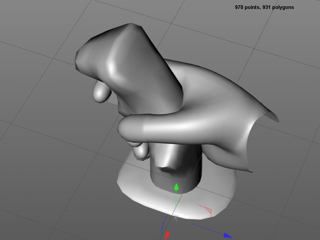
Cobra Cockpit Switches Cube Map Shadow Problem on Android
After spending several days optimizing the Joystick Hand object point and polygon count, I wanted to do some programming again for a change. I decided to finally look into the weird problem I have been having with the shadow mapping of the Cobra cockpit switches. I have two shaders for the Cobra cockpit, one that handles the large illuminated panels and other big rectangular polygons, and another shader for the small switches and such. The main difference between these shaders is that the first uses only a single color plane of the texture atlas for all (greyscale) color info, while the second shader uses the texture as standard RGB color info. The shadow algorithm on both of these shaders was similar, but for some reason the second shader calculated the shadow locations wrong, but only on Android, both worked fine in the Unity editor!
I first noticed this problem back in February but did not want to bother with solving it at that time. Now that I took the problematic shader as a basis for my Cruiser Bridge shader, I noticed that the problem happened there as well. Debugging the problem was rather difficult, as I could not run the game in the Unity editor, I had to keep uploading it to my Android phone and test it there.
It took quite a lot of debugging and trial and error to finally close in on the problem, but I still don't actually understand what exactly causes this weird behavior. I began by making the Cruiser Bridge shader a duplicate of the working CobraCockpit shader, and then began modifying it to look more and more like the misbehaving shader. I found out that leaving out this code in the fragment shader makes the problem appear:
col = col.r > 0.5f ? col : col * dot(i.normal, i.cameraDir);However, that did not make much sense, as that code has absolutely nothing to do with the shadows, it just adjust the brightness of the surface slightly based on the angle between the surface and camera, for a poor man's Global Illumination -type effect. How could leaving some unrelated code out cause any problems? I even checked the resulting compiled code, and the only difference between the two versions were that the used temporary variables were a bit different.
After a lot of further debugging I then finally found the root cause and the root difference between the shaders. In the working vertex shader I had this:
o.uv = float3(2 * v.uv, 1);
However, in the vertex shader that caused the fragment shader to calculate the shadows wrong I had this:
o.uv = 2 * v.uv;My understanding of the shader language is not good enough to see what is so horribly wrong in the second vertex shader code that it will cause havoc with some other code in the fragment shader. In any case, I moved the UV coordinate multiplication from the vertex shader to the fragment shader, and after that the shadows began to work properly! I then realized that it is actually silly to multiply the UV coordinates in the shaders at all, why not just use the correct UV coordinates in the object mesh in the first place? Thus, I changed all the UV coordinates of my CockpitSwitches object and removed the multiplication completely.
Cockpit Texture Reorganization
As I had begun working on the Cruiser Bridge and had decided to use the same texture atlas for all my cockpits, I noticed that the current texture locations were far from optimal. I had put the original Cobra cockpit illuminated panels here and there on the texture atlas, so that there were only small separate areas where all the RGB planes could be used for the other cockpits besides the Cobra cockpit. Thus, I spent one day optimizing the texture and moving the UV coordinates around in the Cobra cockpit mesh. I still have about two thirds of the texture atlas reserved for the Cobra cockpit, so that both the Cruiser bridge and the Pirate cockpit will need to get by with the remaining one third of the texture. But both of those other cockpits will be much more modern looking, so they should not need as much switches and such illuminated panels.
This is what the combined cockpit texture currently looks like (in the Unity editor). All the different color planes (and also the Alpha plane which is not visible) contain the illumination maps of the different switch panels, so as a single RGBA image it looks quite messy. It is kept uncompressed to avoid compression artifacts, which would be very visible on such highly detailed texture maps. This makes it annoyingly large at 21.3 megabytes, but I don't think I can help it if I want to have such detailed instrumentation in the Cobra cockpit.
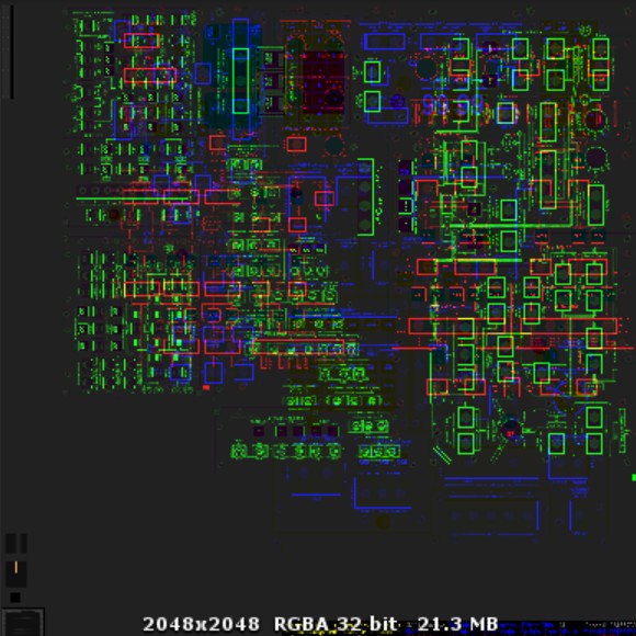
Combined Cockpit Shadow Cube Map
The most recent thing I have been working on was combining the cockpit shadow cube maps into a single cubemap. I have had the Cobra cockpit shadow cubemap as six separate 512x512 resolution images (basically containing a black and white image, but still using all the RGB color planes), using the Unity legacy CubeMap asset, which had also taken a lot of memory as it seems like the legacy cubemap asset does not compress the textures it uses. Now that I needed another such cubemap for the Cruiser bridge shadows, it occurred to me, that I could easily use just a single cubemap, with each of the three cockpits using their own color plane. Thus, I decided to get down to 256x256 resolution (actually, the original cruiser bridge shadow cubemap I made was only 128x128 resolution), and use the current Unity CubeMap texture type, to be able to get the cubemap compressed. I decided to use the red color component for the Cobra cockpit shadow map, green for the Cruiser, which then leaves blue for the upcoming Pirate ship cockpit shadow map. I wrote a short editor helper script to handle creation of the combined cubemap texture from six separate faces for each of the cockpits, and got a 256x256 cubemap which only takes 192 kilobytes of memory.
The next step is to adjust the shadow cubemaps both for the Cruiser bridge and for the Cobra cockpit to more closely follow the cockpit shape. My cockpits are obviously not exactly cube-shaped, so this creates some issues when using a cubemap for the shadows. I am currently trying to figure out a better algorithm to calculate the cubemap light ray hit position for such non-rectangular cockpits.
That's all for now, thanks again for your interest in my project!
Mar 25th, 2018 - Creating a Space Station
Modeling
Immediately after I finished the previous blog post, I began working on the new space station model for LineWars VR. If you remember the original LineWars II, you may remember it having a space station that was basically just a cube, with a "mail slot" for the fighter ships to fly through. That model only had 20 vertices (or points), so it was very cheap to process on the old DOS PC machines. However, for LineWars VR I wanted to have better and more complex space station. I thought the space station design in the movie "2001: A Space Odyssey" looked good and made sense scientifically, and as it has been copied by many games and movies since, I thought I'd do something similar for LineWars VR as well.
Modeling the new space station took only a day or so, as I could just use a collection of primitime shapes (cylinders, toruses capsules, and some cubes) in Cinema 4D. After I got these looking like a simple space station, I made the object editable, and split it into a single quarter of the station, using two symmetry deformers to then generate the full station. That way I only needed to hand-model one quarter of the station. I also wanted to keep the object as low-poly as possible, as the recommended maximum number of vertices per scene for a Gear VR game is a hundred thousand. As I will have many other objects in addition to this space station in a scene, it should only have a fraction of that amount of vertices. On the other hand, there is never more than one space station in a scene, so it can have more polygons and vertices than the other game objects.
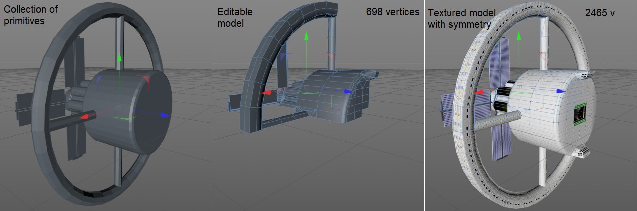
My resulting space station model has 2465 vertices in Cinema 4D. Since all the sharp edges and also all vertices where the texture UV coordinates are not continuous generate extra vertices, the vertex count when the object got imported into Unity went up to 6310. That is pretty high, but still acceptable if I can keep the fighter ships very low-poly.
Texturing
After I got the modeling done, I began texturing the station. The outer rim should obviously have windows, as those are the living quarters. Since I did not have enough polygons to model the windows, I knew I needed this object to use normal mapping for all the small details. In addition to normal mapping, I knew I also needed luminance, as many of the windows should have light in then, even when that side of the station is in shadow. Also, the windows should have specular reflections (same as the solar panels), so that when the sunlight hits them in the correct angle, they should look bright even when there is no light coming from behind the window.
I added all those four 2048x2048 textures (diffuse color, normal mapping, luminance and specular strength) into Cinema 4D, with the plan of using just a 1024x1024 corner area of the texture maps for my station. I plan to have these same textures as a texture atlas for all ships in my game, as there are only four types of ships: Cobra, Pirate, Cruiser and the space station. There will also be alien ships, so if I can fit those into the same texture atlas that would be good, but if needed I can use a different texture for those.
I wanted to be able to shoot at the various parts of the station and have them take damage, so I tried to re-use the same texture panels everywhere I could, to leave room for various damaged panels in the texture atlas. This also meant trying to keep all the panels rectangular, and also not using continuous UV coordinates, so that I can then just change the UV coordinates of a single panel when it gets hit. The solar panels and fuel/water tanks would probably take damage differently. The tanks could simply explode, leaving nothing much behind, and the solar panels could just get torn away when they get hit.
I also planned to have the "mail slot" side of the station always facing the sun, so that I could keep the tanks always in shadow. This meant that I had to have some other way to make the fuel tanks visible, and I decided to add some spot lights shining on them. I modeled these lights in Cinema 4D, and then baked the lighting into a texture, and then copied the relevant parts of the texture into my texture atlas. I had to make some adjustments to the generated texture coordinates to make the texture fit nicely within my texture atlas. I did similar work for the landing pads that are inside the space station.
Finally, as I did not want to load all four different texture maps in the shader, I tried to figure out a way to pack the textures into fewer actual texture maps. With the asteroid I had used the RGB texture planes as the normal directions, and the alpha channel as the grayscale color. This would not work all that well with my station, as I needed to have full RGB color available. It then occurred to me, that perhaps I could get by with just two texture maps? The luminance and specularity were practically on/off toggles, or at most grayscale values, so that left two full RGB and XYZ planes. That totals 8 different panels, which would nicely fit into two RGBA textures. With the ETC2 texture compression the RGB colors of a pixel are compressed into 4 bits and the Alpha channel into another 4 bits, which means that the alpha channel has much less compression artifacts than the RGB channels. Thus, I decided to use the alpha channels of both the textures for the normal vector (as compression artifacts are most noticeable in the normal map). Thus, my resulting texture packing uses the first texture as the RGB diffuse color plus X coordinate of the normal vector, and the second texture as luminance toggle in the Red channel, normal vector Z coordinate in the Green channel, specular strength in the Blue channel, and the normal vector Y coordinate in the Alpha channel.
Shadows
The space station would look pretty bad if it didn't have shadows on the solar panels, when the sun is shining from the front of the station. My plan is to avoid using proper shadow maps in my game, as those would require rendering the scene separately from the view point of the sun, and then using this shadow map to determine which pixels are in shadow, and all of this should be done for every frame. I don't think the mobile devices running Gear VR have the performance to handle this with sufficient quality (meaning large enough shadow maps). So, what are the alternatives?
One thing I could have done would have been to point the station directly towards the sun, and then just bake the shadow information into the texture maps. However, as I wanted to have the solar panels stay stationary while the rest of the station rotates, this would not work. Next, I tried using a static shadow map texture, which would rotate as the main part of the station rotates. Since I use the Dynamic Soft Shadows Based on Local Cubemap method for the cocpit shadows, and that basically just calculates the correct shadow map position from the fragment position in 3D, I thought I could perhaps use something similar but just with a simple texture, when I know the sun always shines from the same direction. I got this working fine, but the problem was the uneven shadow edge around the circular main body of the station. Straight lines looked pretty good, but the circular section had very obvious jagged edges.
I then got the idea of using code instead of a texture map to calculate whether a pixel is in shadow. Since my station only has simple shapes (from the shadow perspective), it has a ring, a central circle, and four poles, I thought that the required formula should not be overly complex. And I was right, I was able to have just a couple of if clauses to check the shadow areas. This resulted in very clean and sharp shadow edge, which was just what I was after.
The Shader
I created a new custom shader to handle all the afore mentioned ideas. I used the asteroid shader as the basis, as it already handled the normal mapping. I had found a slightly more efficient method of handling the tangent space lighting calculations for the normal mapping since my original asteroid blog post, though. Instead of converting the tangent space normal into world space in the fragment shader, it is more efficient to convert the light vector into tangent space in the vertex shader. Unity provides a TANGENT_SPACE_ROTATION macro for this purpose, so the vertex shader calculations can be done simply by the following code, with no need to calculate the binormal vector:
	TANGENT_SPACE_ROTATION;
	o.lightDirection = mul(rotation, mul(unity_WorldToObject, _WorldSpaceLightPos0).xyz);
Then in the fragment shader, this can be handled simply by taking the dot product of the normal vector (taken from the texture) and this light vector:
	fixed4 tex = tex2D(_MainTex, i.uv);
	fixed3 tangentSpaceNormal = tex.rgb * 2 - 1; // Convert the normal vector values from 0..1 to -1..1 range
	fixed4 col = tex.a * (DotClamped(normalize(i.lightDirection), tangentSpaceNormal) * _LightColor0;
The space station vertex shader has four different sections to handle the special requirements of the station model and textures:
- The non-rotating solar panels are handled by using unity_WorldToObject matrix for those vertices to get their coordinates in object space, while the rotating vertices already have their coordinates in object space. This same handling needs to be done also to the normals and tangents of those vertices, which adds so many GPU cycles that I am thinking of eventually abandoning this idea of using a single mesh for the whole station.
- Next, the blinking polygons (or more accurately their vertices) are handled by checking the vertex color Green value (which I use in the c# script to mark the blinking polygons), and if it is set, and the _SinTime.w variable is > 0.99, I move the vertex UV coordinates to a blinking area of a texture map. This generates a short flash once every two seconds or so.
The next step is to prepare the shadow calculation values. The shadow calculation in the fragment shader needs to know which areas of the space station cause a shadow on the polygon, for example polygons in front of the ring poles are not shadowed by the ring poles. Here again I use the vertex colors (this time the Red channel) to select the correct shadow area. This step also prepares the object space vertex coordinate and the object space light direction (which is not the same as the tangent space light direction) for the fragment shader.
Since the tangent space surface normal can point towards the sun even when the polygon itself is in shadow, this can create unrealistic lit pixels on otherwise shadowed polygons. To avoid this, I also calculate a shadow multiplier at this stage, like this:
saturate(50 * dot(_WorldSpaceLightPos0.xyz, worldNormal))
- Finally, I calculate the specular color, based on the world coordinates of the camera, vertex and the light. For better quality specular reflection (especially for curved surfaces) this should be calculated per pixel in the fragment shader, but since my specular surfaces are flat, I thought I could use this optimization.
Then in the fragment shader I first read the two texture maps, and get the tangent space surface normal for this fragment (pixel). This looks rather similar to the asteroid fragment shader above, except I have two textures that get combined:
	fixed4 col = tex2D(_ColorTex, i.uv);
	fixed4 texn = tex2D(_NormalTex, i.uv);
	fixed3 tangentSpaceNormal = fixed3(col.a, texn.a, texn.g) * 2 - 1;
The shadow is then calculated, projecting the fragment position onto the plane that generates the shadow (which the vertex shader has given us), and then checking the coordinates of this projected point whether it is inside the radius of a circular section or whether the X and Y coordinates fall within rectangular sections (the poles, for example). These coordinate areas are currently hard-coded into the shader, but as I would like to use the same shader also for the other ships, I may need to figure out a better system for this. In the fragment shader I call my subroutine CheckShadow to handle the shadow calculation, which returns a value between 0 (in shadow) and 1 (not in shadow), with the not-in-shadow taken from the shadow multiplier calculated in the vertex shader.
	// Handle shadow
	fixed sh = CheckShadow(i.objectPosition, i.objectLightDir, i.shadowData);
Then it is just a matter of checking for luminance (which is not affected by the shadow) and specularity (which is affected by the shadow) to get the final color of the pixel. The luminance uses the second texture Blue channel, and the specularity the second texture Red channel multiplied by the specularity value pre-calculated in the vertex shader.
	// Handle luminance
	if (texn.b > 0.5)
	    return i.specular * texn.r * sh + col;
	// Handle specular
	col = sh * (i.specular * texn.r +
	// Handle bumpiness
	col * DotClamped(normalize(i.lightDirection), tangentSpaceNormal) * _LightColor0);
	return col;
The resulting fragment shader takes only 8.5 GPU cycles worst case, and only 2.5 GPU cycles best case, according to the Mali Offline Compiler. These are pretty good values in my opinion, considering all the stuff the shader needs to handle. The vertex shader however takes 30 GPU cycles, most of which is caused by the rotating/non-rotating part handling, which I could get rid of completely if I had the station in two parts. However, if I split it into two parts, I would have to come up with some different way of handling the rotated shadows on the stationary solar panels, and as even the solar panel part of the station has more than 300 vertices, it could not be batched into the same draw call as the rest of the station. So, I would get rid of one problem and generate two new problems, so I am not yet sure if that change would be worth it. This is the Mali Offline Compiler result for the fragment shader:
  3 work registers used, 1 uniform registers used, spilling not used.

                          A       L/S     T       Bound
  Instructions Emitted:   24      5       2       A
  Shortest Path Cycles:   2.5     2       2       A
  Longest Path Cycles:    8.5     5       2       A
The Result
Here below is a small video of me running the game in the Unity editor (using my Oculus Rift), and recording the editor window. It shows me flying around the space station, so you can see the shadows, luminance and specular handling in action. The specular reflections are visible on the solar panels and on the various windows, while the luminance shows on the windows of the shadow side of the station, and also on the fuel/water tanks.
The next step is to start working on the damaged textures, to handle the effects of ships shooting at the station. This will probably keep me busy for the next couple of weeks, and after that I can hopefully move on the creating the cruiser. I keep learning new tricks every step of the way, so after I have done the cruiser and the fighter ships, I probably have learned a lot of new tricks I can use to improve my space ship cockpit textures and shader. As always, thank you for your interest in my project!
Mar 8th, 2018 - Splitting Asteroids
Game code from LineWars II to Linewars VR
Most of my time during the last month and a half has been spent working on code that handles laser rays hitting an asteroid, but before I started working on that, I ported some of the game logic code from my old Linewars II over to LineWars VR. I started with the Demo scene, where a group of Cobra fighters attack a pirate starbase defended by some Pirate fighters. It took about a week to get the code working. The main issue was changing the original Euler angles for ship directions to use the Quaternions that Unity uses. This needed quite a bit of trial and error to get working, with me trying to understand how the quaternions actually work.
After I got the game code mostly working, I also added a HUD display, which shows the type, distance and speed of a ship that is directly in front of the player's ship. This HUD information is displayed around the crosshairs, just like it was in the original LineWars II.
Asteroid hit work
Then I began working on the main feature of this blog post, the laser hitting an asteroid. I had an idea of doing this in three phases:
- Determine where (on which polygon) the laser hits the asteroid, and play a hit animation at that position.
- If the asteroid is sufficiently large, generate a crater around this hit position.
- Explode the asteroid into fragments, when a big asteroid has been hit several times, or straight after the first hit if the asteroid is very small.
Determining the hit position
Unity does have a physics system that could handle most of this stuff pretty much automatically, but I decided not to use that, as I am not sure about the performance of the system on mobile devices, and the system is pretty much a black box. I like to know exactly what the game code is doing, so I decided to port the collision code from my original LineWars II over, and then start enhancing that with more features.
The first step was to determine whether the laser ray actually hits the asteroid, and if so, where. For a rough collision test I use a simple bounding sphere (as my asteroids are somewhat round in shape). If it looks like the laser ray is close enough to the asteroid center point, I then use a more exact collision detection. I found a good algorithm for a ray-triangle intersection test from the Unity Answers pages. I could use this algorithm pretty much as-is, I just added a test that the triangle and laser do not face the same way (as that would mean the laser hits the back side of the asteroid, which is not what I want). This test removes about half of the triangles from the test, and thus saves some CPU time. I used the System.Diagnostics.Stopwatch to check the number of ticks these tests take (when run in the editor), and the full intersection test for all 528 triangles of the asteroid takes between 1218 and 1291 ticks, while the intersection test leaving out the triangles facing the wrong way takes between 765 and 915 ticks.
Using this ray-triangle intersection test I was able to determine which triangle of the asteroid got hit, and I can even get the exact hit position in world coordinates quite easily. I then used a scene from Star Wars Episode 2 to check the timing of the hit flash and the speed of the explosion fragments, and tried to generate something similar in Cinema 4D using the Explosion FX deformer on my asteroid mesh, together with some flash footage. Below is an animated gif of the hit animation I came up with. This will be played on a quad facing the camera whenever a laser ray hits the asteroid. (Note that the speed of this animated gif is not necessarily the same as what the speed of the animation is inside the game. The animation should last one second, but your browser may run it faster or slower.)
I even added code to my shader rendering the animation, so that the color of the fragments varies depending on how much sunlight falls on the surface of the asteroid that got hit. So, if the laser ray hits a shadow side of the asteroid, you see a flash, but the ejected fragments are almost black. However, hitting a brightly lit side of the asteroid shows bright fragments ejecting from the hit position.
Creating craters
Next, I started working on the code that would dynamically generate craters into the asteroid mesh, around this hit position. I decided to aim for a crater with a radius of 5 meters (or Unity units), which meant that I had to have a way of finding the vertices, triangles and edges that fall within this radious from the hit position.
Since I only knew the one triangle that got hit, and Unity meshes do not have a way of easily finding adjacent triangles, I added a list called V2t (for Vertex-To-Triangles) into my asteroid GameObjects, which I fill when creating the asteroids. This list contains a list of triangles that each vertex in the mesh is a part of. This way I could easily find the adjacent triangles of my hit triangle. However, I soon realized that this was not enough, as my asteroids consist of several texture UV sections, which meant that Unity has duplicated some of the vertices. Thus, I needed to add still another list, keeping track of all the duplicates of each vertex, to be able to locate an adjacent triangle even if it does not share vertices with the current triangle. These two additional lists began to make things rather more complex than I would have liked.
Well, now that i could find the adjacent triangles, the next step was to find the edges of the triangles that get intersected by the crater rim, so that I could then split the triangles along the crater rim. I obviously wanted to have separate triangles for inside and outside the crater rim. For this intersection test I found a good ray-Sphere Intersection Test algorithm, which I could modify to test for intersections along the edges. Thus, my algorithm basically consisted of checking whether each corner vertex (p1, p2 and p3) of a triangle is inside or outside of the crater (with midpoint at p0) like this:
    // Check how many vertices are inside the crater.
    int tst = ((p1 - p0).sqrMagnitude < mhd.craterSqrRadius ? 1 : 0) +
              ((p2 - p0).sqrMagnitude < mhd.craterSqrRadius ? 2 : 0) +
              ((p3 - p0).sqrMagnitude < mhd.craterSqrRadius ? 4 : 0);
This gave me a number between 0 (no vertices are inside the crater) and 7 (all vertices are inside the crater), with the bits
of the tst value determining which edges are intersected by the crater. This I could then use in a switch statement
to try to handle each of the separate cases. Here below is an image from my quad grid notebook where I had doodled some examples
of these different intersections, in an attempt to figure out how to handle them, and to help me to keep track of which vertex is
which when implementing the code.
As you can see from the above image, even if no vertices of the triangle are inside the crater, it is still possible that the crater rim intersects one or more of the triangle edges. Thus, I added the code below, using the Ray-Sphere intersection test, to calculate another variable tst2, which keeps track of how many intersections there are on each of the triangle edges.
    // Check for edge intersections.
    // When tst == 0, usual tst2 values are 9 (100 100), 18 (010 010), 27 (110 110), 36 (001 001), 45 (101 101), 54 (011 011) and 63 (111 111).
    t12a = RaySphereIntersect(p1, (p2 - p1), p0, mhd.craterSqrRadius, out t12b);
    t13a = RaySphereIntersect(p1, (p3 - p1), p0, mhd.craterSqrRadius, out t13b);
    t23a = RaySphereIntersect(p2, (p3 - p2), p0, mhd.craterSqrRadius, out t23b);
    int tst2 = (t12a > 0.0f && t12a < 1.0f ? 1 : 0) +
               (t13a > 0.0f && t13a < 1.0f ? 2 : 0) +
               (t23a > 0.0f && t23a < 1.0f ? 4 : 0) +
               (t12b > t12a && t12b < 1.0f ? 8 : 0) +
               (t13b > t13a && t13b < 1.0f ? 16 : 0) +
               (t23b > t23a && t23b < 1.0f ? 32 : 0);
So, now things began to get quite complex, as I had to handle all these different cases, and not just for the triangle that got
hit, but for all the adjacent triangles as long as there are triangles that have any edge intersections around the original triangle.
I spent a couple of weeks working on this code, and got it to work reasonably well on the original asteroid mesh, but when trying
to generate a new crater that overlaps an existing crater, I ran into such severe problems (stack overflow, and other hard to trace
occasional bugs in my code), that I eventually decided to abandon this code for now. That was pretty frustrating, as I would really
have liked to have craters appear on the asteroids when shooting them.
Exploding the asteroid
Instead of fighting with the crater creation for weeks and weeks, I decided to start working on code that would then eventually split and explode the asteroid. I wanted have a sort of a crumbling effect, so that the asteroid does not simply blast into small polygons, but instead crumbles in a convincing way for a large asteroid. This meant, that I had to divide the changes to happen over several frames, not everything at once. I decided to do this also in three parts:
- Since my asteroid has six separate texture UV sections, I decided to split the asteroid initially into six fragments along the UV sections, as those section rims already had duplicated vertices.
- During the next step, I build proper asteroid fragments from these six sections. This basically means connecting all the rim vertices to a new fragment-specific vertex at the center of the asteroid.
- For every frame after that, I move the six sections away from each other, and start splitting triangles away from the rims.
The first part was pretty easy, as I could just check each vertex, and determine the section it belongs to using it's UV coordinates. I created six separate lists for the vertices of each section, and since the sections were aligned along the local axis of the asteroid, it was easy to determine the direction where the section should move.
During the second frame after the explosion has started, I then generate the new center vertex, and generate new triangles to join all the rim vertices to this new center vertex, for all the six parts. For determining the rim vertices I could use my vertex duplicate lists, since if a vertex has a duplicate, it must be a rim vertex. My algorithm first looks for any duplicated vertex, and then starts traversing the rim (taht is, looking for an adjacent duplicated vertex) until we get back to the original vertex. Here I had to handle one special case, since in a corner triangle all three vertices are on the rim. I had to make sure I follow the correct edge (and do not accidentally cut the corner). I then add new vertex duplicates for each of these rim vertices (to get a sharp angle with different normal directions), and create the new triangles. The normal and tangent directions of the center vertex were a bit problematic, until I decided to just point the normal away from the sun, which has the effect of making the center of the asteroid look black from all directions, which in my opinion looks fine.
During all the following frames (until I determine the explosion has run sufficiently long) I randomly select a rim triangle of the section, and remove it from the main fragment body, generate new vertices for it, and start moving it away from the main fragment body. I also make all these separated small fragments smaller every frame, so that they eventually vanish. All this work is done using the single mesh, so even though it looks like many separate parts, it actually still is just a single GameObject in Unity.
Since the asteroid originally has 528 triangles, and eventually all of these triangles may get separated into a four-triangle fragment, the triangle count can increase up to 528*4 = 2112. Similarly, the original vertex count of 342 can get up to 5280 vertices (as every original triangle becomes a fragment with 10 vertices). Both of these numbers are still within sensible limits though, especially considering that only a few asteroids should be both visible and in the explosion phase at any given time in the game.
Here below is a YouTube video illustration of my asteroid explosion routine in action:
Jan 26th, 2018 - Cobra cockpit work
Cockpit model from my Snow Fall project
For the past month or so I have been mainly working on creating the Cobra cockpit mesh, and texturing it. I started with the main components of my Snow Fall project ship cockpit (which in turn is loosely based on the real Space Shuttle glass cockpit). I think this sort of a retro ship cockpit, without any fancy holographic instruments, suits the feel of my game the best. The first problem I had was with the correct scale of the cockpit. After many tests and trials I ended with an instrument panel that is about 3 metres wide (as the ship is a two-seater) in Cinema 4D, but as that felt a bit too big in Gear VR, I scaled it by 0.9 when importing the mesh to Unity. That size seems to be at least close to correct.
I redid almost all parts of the model, trying to get by with as few vertices as possible. I also decided to use flat shading for the cockpit, based on the excellent Flat and Wireframe Shading tutorial from Catlike Coding (Jasper Flick). That way I don't get duplicated vertices for sharp edges in the mesh when Unity imports it, rather I can disable normals in the mesh completely, and then calculate them as needed in the fragment shader.
Dynamic Soft Shadows Based on Local Cubemap
I had found this interesting blog post on the Arm Mali community about Dynamic Soft Shadows Based on Local Cubemap. This is a trick of getting proper dynamic shadows that emulate the light shining into a room through some windows, using a baked cube map instead of any real time shadow calculations. I thought it might fit my use case pretty well, as I wanted have the sunlight coming through the cockpit windows hitting the instruments and walls of my cockpit. The problem I have, is that my cockpit is not exactly rectangular, and the original algorithm expects a rectangular room for which it calculates the correct shadow position, using a Bounding Box of the room size. I do have some ideas about how to solve this issue, though, but haven't yet had time to fully implement my ideas. I do have the basic system working already, though, and it looks pretty neat in my opinion!
The blog post (and the corresponding Unity sample project) also gives code for calculating dynamic shadows for moving objects, which I think I might need for getting proper shadows from all the switches, the joystick, the pilot's body parts, and such. To be ready for this, I decided to split my cockpit into two meshes, one containing the base cockpit structure, using the flat shading, and another containing all the separate switches and other (possibly even moving) objects which should generate shadows on the various cockpit panels. I decided to use a different shader for this object, with normals, as most of these objects should not be flat shaded. This of course adds one Draw Call, but I don't think having an extra Draw Call for the cockpit is that much of an issue, considering the cockpit is the closest object to your eyes, and thus should be the most detailed.
I have already tested these dynamic shadows as well, but the code has a lot of issues (for nicer results I should up the shadow texture resolution to 2048x2048 pixels, but that would cause a rather significant extra work for the GPU, and even so the shadows sometimes are not at exactly the correct position), so I am not yet sure if I will actually implement this part of the code at all. I think with the issues and slowdown the trouble is perhaps not worth the effort. Besides, even John Carmack has said "Don't try to do accurate dynamic shadows on GearVR. Dynamic shadows are rarely aliasing free and high quality even on AAA PC titles, cutting the resolution by a factor of 16 and using a single sample so it runs reasonably performant on GearVR makes it hopeless."
By the way, there was one issue with the dynamic shadows that I fought with before I managed to solve it, the shadow texture was upside down on my Oculus Rift (which I use for quick tests)! I spent a bit too long googling for this issue, considering it is a known issue, the texture coordinates have the V coordinate reversed in the Direct 3D system, compared to Open GL for which the original algorithm and shaders were coded for. I managed to fix this issue by replacing this code (in the original RoomShadows.shader):
	// ------------ Runtime shadows texture ----------------
	// ApplyMVP transformation from shadow camera to the vertex
	float4 vertexShadows = mul(_ShadowsViewProjMat, output.vertexInWorld);

	output.shadowsVertexInScreenCoords = ComputeScreenPos(vertexShadows);

	return output;
}
with this code (I needed to base my change on ComputeNonStereoScreenPos() instead of the original ComputeScreenPos(), which uses separate coordinates for each eye when in VR, and thus displayed the shadows in one eye only!):
	// ------------ Runtime shadows texture ----------------
	// ApplyMVP transformation from shadow camera to the vertex
	float4 vertexShadows = mul(_ShadowsViewProjMat, o.vertexInWorld);

	o.shadowsVertexInScreenCoords = ComputeNonStereoScreenPosNew(vertexShadows);

	return o;
}

inline float4 ComputeNonStereoScreenPosNew (float4 pos) {
	float4 o = pos * 0.5f;
	#if defined(UNITY_HALF_TEXEL_OFFSET)
		o.xy = float2(o.x, o.y /** _ProjectionParams.x*/) + o.w * _ScreenParams.zw;
	#else
		o.xy = float2(o.x, o.y /** _ProjectionParams.x*/) + o.w;
	#endif
	o.zw = pos.zw;
	return o;
}
That is, I commented out the ProjectionParams.x multiply, so the shadow texture is always read the correct way up.
Cockpit texture packing
Same as with my Snow Fall project, I want to have the cockpit of my LineWars VR game as detailed as I can make it (without sacrificing performance, obviously). Even as a kid I built all sorts of plane cockpits (using cardboard boxes) with detailed instruments, so my interest in detailed cockpits must be trying to fulfill some sort childhood dream of sitting in a cockpit of an aeroplane. :-) Anyways, for my Snow Fall project I had purchased a book called The Space Shuttle Operators Manual which has detailed schematics for all the instrument panels of the Space Shuttle. I had scanned these pages and converted them to emissive textures for my Snow Fall project, but in LineWars VR I needed them to have also some other details, so I decided to re-scan the schematics. (By the way, it seems that the same schematics can be found from this PDF from NASA, which even has the new glass cockpit instrumentation, which my original book did not have: Space Shuttle Crew Operations Manual).
After scanning all the schematics of the panels I wanted to have in my Cobra cockpit, I tried to fit them into a single rectangular texture (in Snow Fall all the textures were separate, with various sizes, most over 2048 pixels per side, and there were dozens of these textures!). I noticed I could just about fit them with still readable texts and symbols if I used a 4096x4096 texture. However, a texture of this size would take 48 megabytes uncompressed, and as all the recommendations for Gear VR state that textures should be kept at 2048x2048 or below, I began looking into ways to make the texture atlas smaller.
I decided to go with "gray packing", as most of the information in my textures has to do with the instrument panel switches illumination, and all the panels themselves are pretty much just gray. Thus, I created a C# script for Unity, which reads my 4096x4096 uncompressed BMP texture, and generates a 2048x2048 32-bit image from it, with each 2048x2048 area of the original image in one of the Red, Green, Blue and Alpha channels. Using ETC2 compression, I was able to get practically all the information from the original 48MB BMP file into a 4MB texture! The actual packing routine is pretty simple, it just gets the input bytes array, offset into the BMP file where the actual data starts, and width and height of the original file, and it packs the data into the four pixel planes into outbytes array (with room for the 54-byte BMP header):
    private void Convert(byte[] outbytes, byte[] inbytes, int inoffs, int w, int h)
    {
        // BMP pixel format = Blue, Green, Red, Alpha
        for (int y = 0; y < h; y++)
        {
            for (int x = 0; x < w; x++)
            {
                outbytes[54 +
                    (4 * (w >> 1) * (y & ((h >> 1) - 1))) +
                    (4 * (x & ((w >> 1) - 1))) +
                    (y * 2 < h ? 2 : 0) +
                    (x * 2 < w ? 0 : 1)
                    ] = inbytes[inoffs + 3 * (y*w + x)];
            }
        }
    }
That code is obviously not the most efficient way to do this, but since I only run it in the Unity editor whenever the texture BMP
changes (which does happen often, now when I am working on the textures), it does not matter whether it takes 100ms or 500ms to run.
Of course this packing of the texture also needed some changes to the vertex and fragment shaders, to look up the correct texture coordinates and select the correct color plane, and also to convert the grayscale texture value to the yellowish instrument panel illumination color. In my CobraCockpitShader.shader code I use a vertex-to-fragment structure that looks something like this:
	struct v2f
	{
		float4 vertex : SV_POSITION;
		float2 uv : TEXCOORD0;
		fixed4 channel: TEXCOORD1;
	};
The other items are pretty much standard, but the channel element is the one that handles the color plane masking. It is set up in the vertex shader like this:
	o.uv = 2 * TRANSFORM_TEX(v.uv, _MainTex);
	o.channel = max(fixed4(1 - floor(o.uv.x) - floor(o.uv.y), floor(o.uv.x) * floor(o.uv.y), floor(o.uv.y) - floor(o.uv.x), floor(o.uv.x) - floor(o.uv.y)), 0);
That is, all the texture coordinates are multiplied by two (so they get the range of 0..2 instead of 0..1, to map from 0..4096 to 0..2048 texels). Since the texture parameters use wrapping, the coordinates that are over 1 simply get mapped back to the range 0..1, but I can use these 0..2 coordinate ranges to determine the correct "quadrant" of the texture. The floor function converts the coordinate to integer, so it can only get a value of 0 or 1, and thus the UV coordinates map to one of the four "quadrants" (with the V coordinate reversed for OpenGL texture orientation): (0,1) = Red, (1,1) = Green, (0,0) = Blue, and (1,0) = Alpha. The channel setting uses some arithmetic to get only one of the four color components set, based on which of the UV coordinates were over 1, without using any conditional operations.
Then, in the fragment shader, I take only the wanted color channel from the texture, and switch to yellowish color if the resulting color is above a threshold, like this:
	// sample the texture
	fixed4 col = tex2D(_MainTex, i.uv) * i.channel;
	// Only one of the channels has data, so sum them all up to avoid conditionals
	fixed tmp = col.r + col.g + col.b + col.a;
	// Clamp the colors so we get yellow illumination with gray base color.
	col = min(tmp, fixed4(1, 0.7f, 0.4f, 1));
Cinema 4D C.O.F.F.E.E. UV Plugin
I find modeling pretty easy, but texturing in Cinema 4D is something I constantly struggle with. Perhaps my workflow especially with this project is not very well suited to the way the UV tools in Cinema 4D work. I have a BMP image containing a texture atlas, and I want to map certain polygons in my model to certain exact UV coordinates in this already existing texture atlas. At first I simply used the Structure view of Cinema 4D to input the coordinates by hand, but that got boring and error-prone pretty quickly. I then decided to look into creating my own plugin to make this job easier.
I managed to create a plugin that finds a point (vertex) that is currently selected in the mesh, and then looks for all the selected polygons sharing this point, and gets the UV coordinates from the UVW tag for this point in the polygon. These coordinates (which are floating point numbers between 0 and 1) are then converted to 0..4096, to match with my texture image, and displayed in a popup window.
Then when I input new coordinates, it sets all the selected polygon's UVW coordinates for this point to the given value (converted back from 0..4096 to 0..1 range). Thus, using this makes it easier for me to map coordinates in the texture atlas to a UV coordinates, and since I can select the polygons that should be affected, I can avoid (or create when necessary) discontinuities in the UV coordinates, which would make Unity duplicate the vertex when importing the mesh. Even though the plugin is a bit buggy and quite rudimentary, it has been a big help in my peculiar texturing workflow.
RenderScale, AntiAliasing and MipMapping
I mostly use my Oculus Rift when working on my project, and only occasionally actually build and run the project on my Gear VR device. I began wondering why my cockpit does not look nearly as nice on Gear VR as it looks on Oculus Rift. The textures were flickering and did not look to be as detailed as on the Rift, even though I used the same textures, and the display resolution should be about the same. Even the skybox showing the background planet had clear aliasing problems, while it was very clean-looking on the Rift.
I first tried to increase the antialiaing (MSAA) level, but that did not seem to have much of an effect. After searching the net for anwsers, I finally found the RenderScale setting, and noticed that using the default 1.0 RenderScale the eye buffer size was only 1024x1024 on the Gear VR, while on Oculus Rift it was 1536x1776 per eye! This obviously caused a big difference in the apparent quality. I experimented with increasing the RenderScale to 1.5, which made the eye texture 1536x1536 on the Gear VR (and something huge, like 2304x2664 on the Rift), and that got rid of the aliasing problem with the skybox, and the textured looked much more detailed, but still there was some texture crawl and star field flickering issues, on both Gear VR and Oculus Rift. On my Galaxy S6, the RenderScale 1.5 also caused an occasional FPS drop, so that would not be a real solution for the texture problems.
I then ran accross the article by John Carmack, where he states that Mip Maps should always be enabled on Gear VR. Well, I did not have them enabled, as I thought the cockpit is so close to the eyes, there is no need to blur any of the cockpit textures. Just to test this, I enabled Mip Mapping, and contrary to my expectations, the textures got a lot calmer and the flickering was almost completely gone. The bad thing was, the texture compression artifacts (caused by my gray packing) got quite visible. At first I thought about doing some clever reordering of the texture atlas that could lessen the artifacts, but in the end I decided to go with an uncompressed texture for the cockpit instrument panels. Sadly, with Mip Mapping, this bloated the original 4MB texture to a whopping 21.3MB! However, I think I can have all my other textures compressed, so perhaps I can get away with one such huge texture in my game.
Cockpit instruments, clock and radar
Occasionally I get bored with working on the textures, and get sidetracked with some other feature that my game needs. One of the things I think every Virtual Reality game should have, is a visible real time clock when you are in VR. I don't know if it is just me, but usually when I am playing a VR game, I only have a certain amount of time I can play it, before I need to do something else. It is pretty annoying trying to check what time it is by peeking out of the VR glasses. Thus, I began experimenting with ways to get a clock display into my cockpit. I had already implemented a simple UI panel into the center MFD (multi-function display), which I certainly could use for a clock, but I wanted to check if there was a way to add instruments without adding any Draw Calls to my project.
The center panel (based on the Space Shuttle center panel) happened to have a slot for a timer, which I had some trouble deciding on how to model or texture. I decided to change this into a digital clock, so I could kill two birds with one stone, so to speak: Have a clock visible, and have the timer area actually do something useful in the center panel. I had an idea of adding the number (and letter) glyphs into my cockpit texture atlas, and then just switching the UV coordinates in my cockpit mesh whenever the clock changes (once per minute). This would neatly avoid any extra draw calls, and I thought that updating the UV coordinates of my base cockpit mesh (which at the moment has 737 vertices and 1036 triangles inside Unity, and 566 points/688 polygons in Cinema 4D) once a minute should not cause much of a slowdown. However, to be able to update just the UV coordinates of certain polygons in the cockpit mesh, I needed a way to find those polygons!
I couldn't use anything like the index of a point or polygon from Cinema 4D to find the clock face polygons, as Unity will rearrange the vertices and triangles when it imports the mesh. I needed to find the correct UV coordinate array indices within Unity, but to do that I needed to have something set up in Cinema 4D to flag the polygons I needed to find. I decided to simply flag the left edge of the clock face polygons with a UV coordinate U value 0.5, as nothing else in my mesh uses that UV coordinate value. Of course I could also have used for example 0 or 1, but as Cinema 4D gives those coordinates to newly created polygons, I did not want to have this cause problems. This is how the polygons were organized in the object inside Cinema 4D (don't mind the Min/Sec headers, the clock will show Hour/Min, I was just lazy to change the texture, as that text is so small it will not be readable in the game):
So, now I only needed to find the corresponding triangles in Unity, find their UV indices (in correct order), store these, and then use these to display a number glyph whenever the current time changes. Sounds simple, but it took a bit of a trial and error to find the simplest algorithm to handle this. In my daytime job I had used C# and Linq quite extensively, so I reverted to my Linq toolbox for these algorithms, as the performance was not critical during this setup phase. Here is the routine I came up with, hopefully sufficiently commented, so that you can see what it does:
    using System.Linq;

    int[,] m_clockUVIndices = new int[4, 4];

    void PrepareClock()
    {
        // Find the clock vertices
        Mesh mesh = GetComponent<MeshFilter>().mesh;
        Vector2[] uvs = mesh.uv;
        Vector3[] verts = mesh.vertices;
        // Find all the vertices flagged with "uv.x == 0.5f"
        List<int> vidxs = new List<int>();
        for (int i = 0; i < verts.Length; i++)
            if (uvs[i].x == 0.5f)
                vidxs.Add(i);
        // Find the polygons that use these vertices, these are the digital clock face polygons.
        List<int> tidxs = new List<int>();
        int[] tris = mesh.triangles;
        for (int i = 0; i < tris.Length; i++)
            if (vidxs.Contains(tris[i]))
                tidxs.Add(i / 3);
        // Now tidxs contains all the triangles (including duplicates) that belong to the digital instrument faces.
        // We need to find the correct order of the triangles, based on the sum of the X and Y
        // coordinates of their vertices.
        tidxs = tidxs.Distinct()
                     .OrderBy(a => verts[tris[a * 3]].x + verts[tris[a * 3 + 1]].x + verts[tris[a * 3 + 2]].x)
                     .ThenBy(a => verts[tris[a * 3]].y + verts[tris[a * 3 + 1]].y + verts[tris[a * 3 + 2]].y).ToList();
        // Next, reorder the vertices of each pair of triangles for our final UV coordinate array.
        for (int i = 0; i < 4; i++)
        {
            List<int> tmp = new List<int>
            {
                tris[tidxs[i*2] * 3],
                tris[tidxs[i*2] * 3 + 1],
                tris[tidxs[i*2] * 3 + 2],
                tris[tidxs[i*2+1] * 3],
                tris[tidxs[i*2+1] * 3 + 1],
                tris[tidxs[i*2+1] * 3 + 2],
            };
            tmp = tmp.Distinct().OrderBy(a => verts[a].x).ThenByDescending(a => verts[a].y).ToList();

            m_clockUVIndices[i, 0] = tmp[0];
            m_clockUVIndices[i, 1] = tmp[1];
            m_clockUVIndices[i, 2] = tmp[2];
            m_clockUVIndices[i, 3] = tmp[3];
        }
    }
Now that I had the UV indices that need changing stored, it was a simple matter to change these whenever the current minute changes. Here below is the code that does that, by checking the current minute against the last updated minute. Don't get confused by the const values having X and Y coordinates, these mean the texture U and V coordinates, I just prefer the X and Y terminology over U and V:
    const float X_START = 2048f / 4096f;	// Start of the number glyph U coordinate
    const float Y_START = 1f - (2418f / 4096f);    // Start of the letter 0 in the texture atlas
    const float X_END = 2060f / 4096f;	// End texture U coordinate of the number glyph
    const float Y_SIZE = -((2435f - 2418f) / 4096f); // Height of the number glyph we want to display
    const float Y_STRIDE = -23f / 4096f;	// How much to travel to find the next number glyph

    int m_currentMinute = -1;

    void UpdateClock()
    {
        DateTime curTime = DateTime.Now;
        if (curTime.Minute != m_currentMinute)
        {
            // Update the clock when the current minute changes.
            m_currentMinute = curTime.Minute;
            Mesh mesh = GetComponent<MeshFilter>().mesh;
            Vector2[] uvs = mesh.uv;
            // Set the lower digit of the minute
            float y = Y_START + Y_STRIDE * (m_currentMinute % 10);
            uvs[m_clockUVIndices[3, 0]] = new Vector2(X_START, y);
            uvs[m_clockUVIndices[3, 1]] = new Vector2(X_START, y + Y_SIZE);
            uvs[m_clockUVIndices[3, 2]] = new Vector2(X_END, y);
            uvs[m_clockUVIndices[3, 3]] = new Vector2(X_END, y + Y_SIZE);
            // Set the higher digit of the minute
            y = Y_START + Y_STRIDE * (m_currentMinute / 10);
            uvs[m_clockUVIndices[2, 0]] = new Vector2(X_START, y);
            uvs[m_clockUVIndices[2, 1]] = new Vector2(X_START, y + Y_SIZE);
            uvs[m_clockUVIndices[2, 2]] = new Vector2(X_END, y);
            uvs[m_clockUVIndices[2, 3]] = new Vector2(X_END, y + Y_SIZE);
            // Set the lower digit of the hour
            y = Y_START + Y_STRIDE * (curTime.Hour % 10);
            uvs[m_clockUVIndices[1, 0]] = new Vector2(X_START, y);
            uvs[m_clockUVIndices[1, 1]] = new Vector2(X_START, y + Y_SIZE);
            uvs[m_clockUVIndices[1, 2]] = new Vector2(X_END, y);
            uvs[m_clockUVIndices[1, 3]] = new Vector2(X_END, y + Y_SIZE);
            // Set the higher digit of the hour (24-hour clock)
            y = Y_START + Y_STRIDE * (curTime.Hour / 10);
            uvs[m_clockUVIndices[0, 0]] = new Vector2(X_START, y);
            uvs[m_clockUVIndices[0, 1]] = new Vector2(X_START, y + Y_SIZE);
            uvs[m_clockUVIndices[0, 2]] = new Vector2(X_END, y);
            uvs[m_clockUVIndices[0, 3]] = new Vector2(X_END, y + Y_SIZE);
            mesh.uv = uvs;
        }
    }
The end result, with the game running on Oculus Rift, and this image captured from the editor, looks like the following (with the clock showing 12:42):
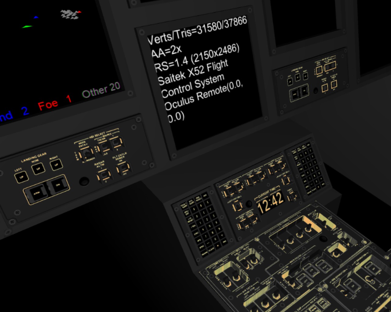
As you can see from the image above (well, besides the badly unfinished texturing of the center console), I also worked on some radar code. The radar display uses much of the same techniques, the legend showing the number of friendly, enemy, and other objects uses the exact same texture UV coordinate changing, and the radar blips actually change the triangle mesh coordinates similarly. That creates a 3D radar view (not a hologram, mind you, just a simple 3D display, which even current day technology is capable of, like in Nintendo 3DS) that shows the direction and distance of the other ships and asteroids. I decided to use logarithmic scale in the radar, so that it is scaled based on the furthest object, and the distances are first square rooted and then scaled based on this furthest distance. This way even objects that are relatively close clearly show their direction relative to your own ship.
Next steps
Well, I will continue working on texturing the cockpit, and occasionally testing some other interesting algorithms, to not get bored with the texturing work (which I really do not much enjoy). I just got an Android-compatible gamepad, and I have already done some basic work on reading the Gear VR Controller, so adding proper input would be something I need to do pretty soon. I have also imported the original Pirate and Station meshes from LineWars II into my project, as placeholders, so I could perhaps start working on the actual game mechanics in the near future.
Lots of work remaining, but at least the project does progress slowly but surely!
Dec 23rd, 2017 - Modeling and Texturing Asteroids
Asteroid references
A week or so ago I began looking into creating asteroids for LineWars VR. In the original Linewars II I had and asteroid mesh that had 12 vertices and 20 polygons. I then scaled this randomly and differently in all three dimensions, to create asteroids of various sizes and shapes. However, for Linewars VR I want to have something a bit more natural looking, so I spent a couple of days looking for ideas and tutorials about asteroid generation. I thought that modeling the asteroid mesh by hand would not create suitable variation, so I mainly looked into procedural asteroid generation. I even found a Unity forum thread about that exact subject, so I was certainly not the first one trying to do that. The Unity forum thread did not seem to have exactly what I was after, though. I also found a tutorial about creating asteroids in Cinema 4D, but those asteroids did not look quite like what I had in mind for LineWars VR.
Procedural textures
Finally I found a thread about procedural asteroid material in Blender, which seemed to have results much like what I was after. So, I decided to first look into creating a suitable texture for my asteroid, and only after that look into the actual shape of the asteroid. The example used a procedural texture with Cells Voronoi noise together with some color gradient. At first I tried to emulate that in Cinema 4D, but did not quite succeed. Finally I realized that the Cinema 4D Voronoi 1 noise actually generated crater-like textures when applied to the Bump channel, with no need for a separate color gradient or other type of post-processing! Thus, I mixed several different scales of Voronoi 1 (for different sized craters), and added some Buya noise for small angular-shaped rocks/boulders. For the diffusion channel (the asteroid surface color) I just used some Blistered Turbulence (for some darker patches on the surface) together with Buya noise (again for some rocks/boulders on the surface).
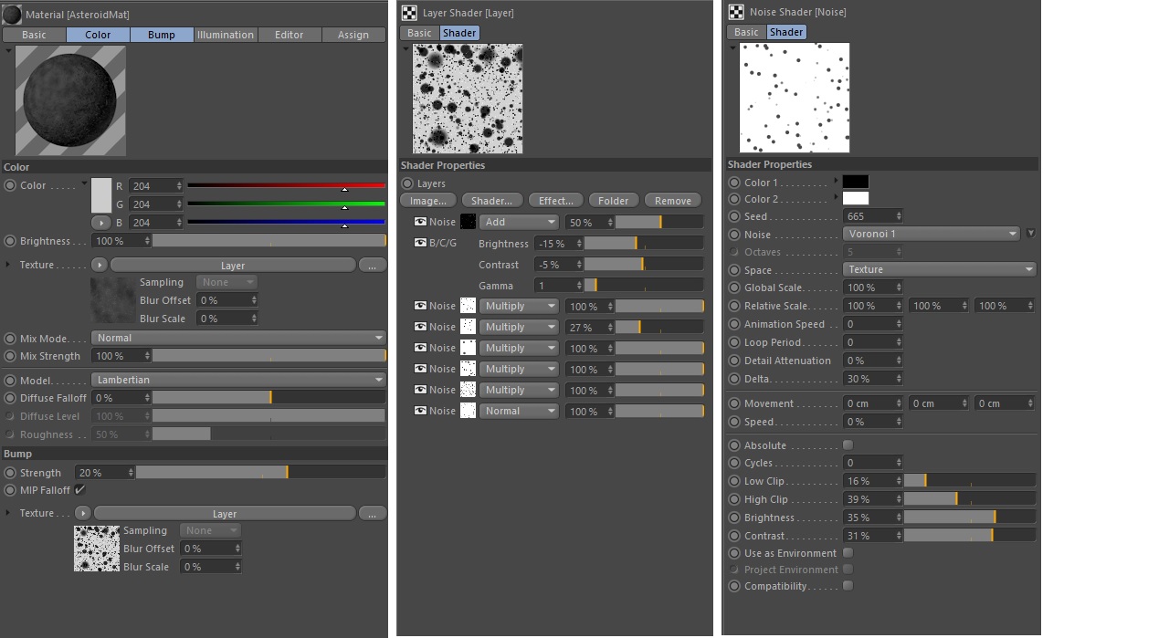
Procedural asteroid mesh
Okay, that took care of the textures, but my asteroid was still just a round sphere. How do I make it looking more interesting? For my texturing tests I used the default Cinema 4D sphere object with 24 segments. For that amount of segments, the resulting sphere has 266 vertices. For my first tests to non-spherify this object, I simply randomized all these vertex coordinates in Unity when generating the mesh to display. This sort of worked, but it generated a lot of sharp angles, and the asteroid was not very natural-looking. Many of the online tutorials used FFD (Free Form Deformation) tool in the modeling software to generate such deformed objects. I could certainly also use the FFD tool in Cinema 4D for this, but I preferred something that I could use within Unity, so that I could generate asteroids that are different during every run of the game, just like they were in the original LineWars II.
I decided to check if Unity would have an FFD tool, and found a reasonably simple-looking FreeFormDeformation.cs C# code for Unity by Jerdak (J. Carson). I modified that code so, that instead of creating the control points as GameObjects for the Unity editor, I created the control points in code with some random adjustments, and then used these control points for deforming the original sphere mesh while instantiating a new asteroid in Unity. After some trial and error with the suitable random value ranges I was able to generate quite convincing asteroid forms, at least in my opinion. This is my current random adjustment, which still keeps the asteroids mostly convex, so I don't need to worry about self-shadowing (as I want to have dynamic lighting, but plan to avoid real-time shadows, for performance reasons):
    Vector3 CreateControlPoint(Vector3 p0, int i, int j, int k)
    {
        Vector3 p = p0 + (i / (float)L * S) + (j / (float)M * T) + (k / (float)N * U);
        return new Vector3(p.x * (0.5f + 4 * Random.value), p.y * (0.5f + 4 * Random.value), p.z * (0.5f + 4 * Random.value));
    }
Exporting procedural textures from Cinema 4D to Unity
Now I had a nicely textured sphere in Cinema 4D, and a nice loking asteroid mesh in Unity, but I still needed to somehow apply the procedural texture generated in Cinema 4D to the mesh deformed in Unity. I first looked into some YouTube tutorial videos, and then began experimenting. Using the Bake Object command in Cinema 4D I was able to convert the sphere object to a six-sided polygon object with proper UV coordinates, together with baked textures.
To generate a normal texture for Unity from the bump channel in Cinema 4D I had to use the Bake Texture command, which gives me full control over which material channels to export, how the normals should be exported (using the Tangent method, as in the screen shots below), and so on.
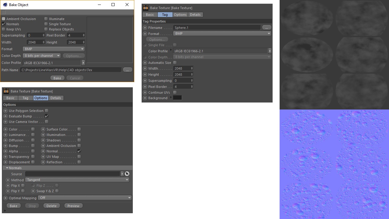
When I imported this mesh into Unity, applied my Free Form Deformation to it (which meant I had to call the Unity RecalculateNormals() method afterwards), and applied the texture to the mesh, there were visible seams where the six separate regions met. After some googling I found a blog post that explained the problem, together with code for a better method to recalculate normals in Unity. I implemented this algorithm, and got a seamless asteroid! Here below is an animated GIF captured from the Unity game viewport (and speeded up somewhat).
Asteroid shader
After I got the asteroid working witht the Standard Shader of Unity, I wanted to experiment coding my own shader for it. I had several reasons for creating a custom shader for my asteroid object:
- I wanted to learn shader programming, and this seemed like a good first object for experimenting with that.
- I had an idea of combining both the diffuse texture and the normal texture into a single texture image, as my diffuse color is just shades of gray. I can pack the 24bpp normal map with the 8bpp color map to a single 32bpp RGBA texture. This should save some memory.
- I wanted to follow the "GPU Processing Budget Approach to Game Development" blog post in the ARM Community. I needed to have easy access to the shader source code, and be able to make changes to the shader, for this to be possible.
- I am not sure how efficient the Standard Shader is, as it seems to have a lot of options. I might be able to optimize my shader better using the performance results from the Mali Offline Compiler for example, as I know the exact use case of my shader.
C:\Projects\LineWarsVR\Help>malisc -c Mali-T760 Asteroid.vert
  4 work registers used, 15 uniform registers used, spilling not used.

                          A       L/S     T       Bound
  Instructions Emitted:   19      10      0       A
  Shortest Path Cycles:   9.5     10      0       L/S
  Longest Path Cycles:    9.5     10      0       L/S

C:\Projects\LineWarsVR\Help>malisc -c Mali-T760 Asteroid.frag
  2 work registers used, 1 uniform registers used, spilling not used.

                          A       L/S     T       Bound
  Instructions Emitted:   9       4       1       A
  Shortest Path Cycles:   4       4       1       A, L/S
  Longest Path Cycles:    4       4       1       A, L/S
So, the vertex shader (which needs to calculate a BiNormal vector for the vertex, based on the existing Normal and Tangent vectors)
takes 10 GPU cycles per vertex to execute (so for 266 vertices in the asteroid, this takes at most 2660 GPU cycles per asteroid,
probably less if the back-facing polygons have been culled in an earlier step of the rendering pipeline), and the fragment
shader (which needs to calculate the TangentSpace normal vector from the normal map and the Normal, Tangent and BiNormal vectors
provided by the vertex shader) takes only 4 GPU cycles per fragment (pixel). As my Galaxy S6 (which is close to the low end of
the Gear VR -compatible devices) has a GPU processing budget of 28 GPU cycles per pixel, my asteroid is well within this budget.
Nov 28th, 2017 - The Beginning
Okay, so I decided to start working on a new game project, after quite a long while. Many times since I coded and released my LineWars II game, I have been thinking about getting back to coding a new space game. However, I hadn't dared to start working on such, as it seems that all games nowadays are built by a large team of developers, artists, and other professionals. I thought that a single person making a game during their free time would probably not have a chance of succeeding in competition against such big game projects. However, I recently ran across End Space for Gear VR, which idea-wise is a rather similar space shooter as what Linewars II was. Reading the developer's blog, I found out that it was actually created by a single person. As there are not all that many cockpit-type space shooter games for Gear VR, and this End Space seems to be rather popular, I thought that perhaps there would also be interest for a Virtual Reality port of my old LineWars II game!
As the Gear VR runs on mobile devices, it means that the graphics and other features need to be quite optimized and rather minimalistic to keep the frame rate at the required 60 fps. This nicely limits the complexity of the game, and also gives some challenges, so this would be a good fit to my talents. I am no graphics designer, but I do like to optimize code, so hopefully I can get some reasonably good looking graphics running fast. No need for a team of artists, when you can not take advantage of graphics complexity. :-)
Music
I heard about End Space at the end of November 2017, and after making the decission to at least look into porting LineWars II to Gear VR, I started looking at what sort of assets I already had or could easily create for this project. Pretty much the first thing I looked into was music. Linewars II used four pieces originally composed for Amiga 500 by u4ia (Jim Young). He gave me permission to use those pieces of music in LineWars II, and I converted the original MOD files to a sort of hybrid MIDI/MOD format, in order to play the same music on Creative SoundBlaster, Gravis UltraSound or Roland MT-32, which were the main audio devices at that time. By far the best music quality could be achieved from playing the music via a Roland MT-32 sound module. However, the only way to play that hybrid MIDI/MOD song format was within LineWars II itself, and I was not sure if I could somehow record the music from the game, now 24 years later!
After some experiments and a lot of googling, I managed to run the original Linewars II in DOSBox, together with the Munt Roland MT-32 software emulator and Audacity, and record the music into WAV files with a fully digital audio path, so the music actually sounded better than it had ever sounded on my real Roland LAPC-1 (an internal PC audio card version of the MT-32 sound module)! So, the music was sorted, what else might I already have that I could use in this project?
Missä Force Luuraa
That is the title of a Finnish Star Wars fan film from 2002. The film never got finished or released, but I created some 3D animation clips for the movie, as I was just learning to use Cinema 4D at that time (as that was the only 3D modeling package I could understand after experimenting with the demo versions of many such packages). Now as I was going through my old backup discs of various old projects, I found the scene files for all these animation clips. Looking at those brought back memories, but they also contained some interesting scenes, for example this tropical planet. This would fit nicely into Linewars VR, I would think, as pretty much all the missions happen near a planet.
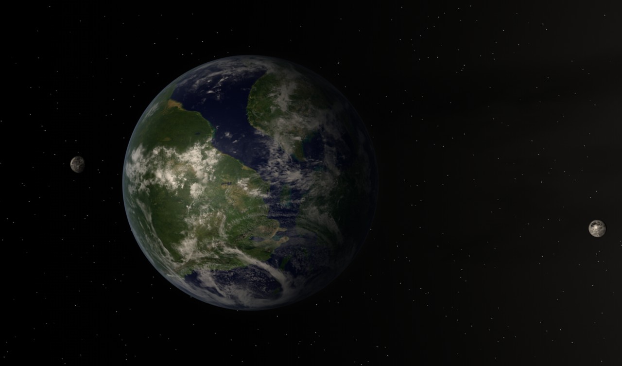
Snow Fall
Back in 2002 I started working on a 3D animation fan film myself, the setting of my fan film "Snow Fall" being the events of a chapter of the same name in the late Iain M. Banks' novel "Against a Dark Background". This project has also been on hold for quite a while now, but I do every now and then seem to get back to working on it. The last time I worked on it was in 2014, when I added a few scenes to the movie. It is still very far from finished, and it seems the 3D animation technology progresses much faster than I can keep up with my movie, so it does not seem like it will ever get finshed.
In any case, I spent a lot of time working on a detailed ship cockpit for this animation project. I believe I can use at least some of the objects and/or textures of the cockpit in my LineWars VR project. This cockpit mesh has around a million polygons, and uses a lot of different materials, most of which use reflections (and everything uses shadows), so I will need to optimize it quite a bit to make it suitable for real-time game engine rendering. Here below is a test render of the cockpit from June 28th, 2003.
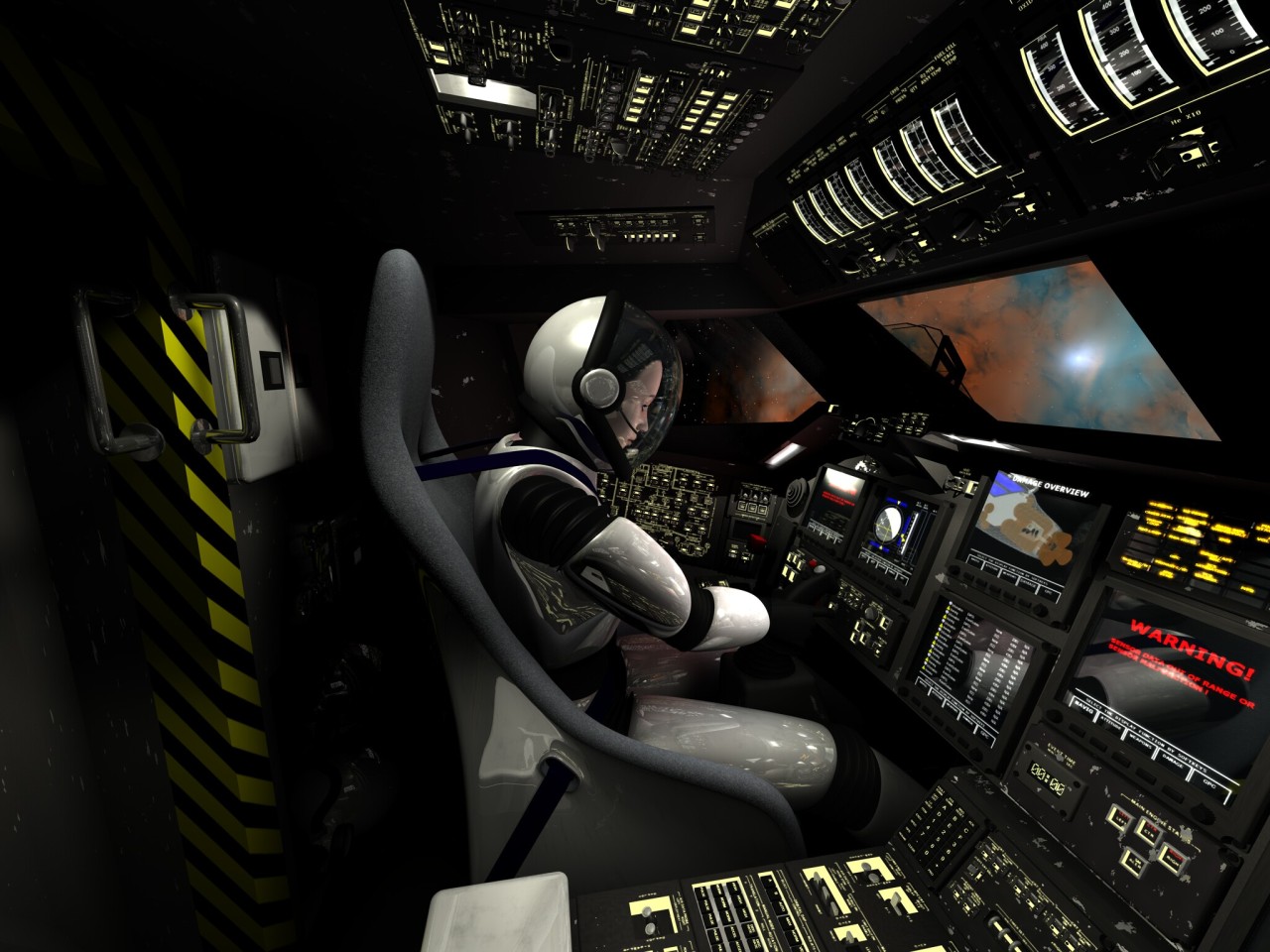
Learning Unity
As I haven't worked with Unity before, there are a lot of things to learn before I can become properly productive with it. I am familiar with C#, though, so at least I shoudl have no trouble with the programming language. I have been reading chapters from the Unity manual every evening (as a bedtime reading :), and thus have been slowly familiarizing myself with the software.
Explosion animation
One of the first things I experimented with in Unity was a texture animation shader, which I plan to use for the explosions. I found an example implementation by Mattatz from Github, and used that for my tests. I also found free explosion footage from Videezy, which I used as the test material. This explosion did not have an alpha mask, but it seems that none of those explosion animations that have an alpha masks are free, so I think I will just add an alpha mask to this free animation myself.